V2 Enclosures:
Below are some creative techniques folks have used to enclose their V2 tachometer kits. If you have a tachometer enclosure you are proud of, feel free to email it to me and I'll post it here (Please let me know how you would like to be addressed).
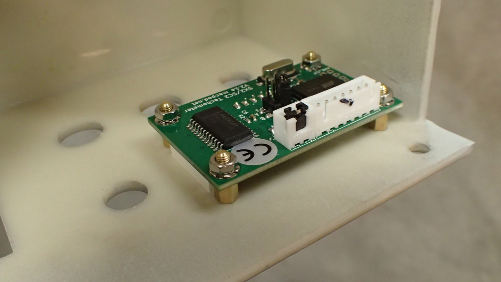
For those who are preparing to make their own enclosures, the following dxf file of the board and hole positions may be useful (The units are in millimeters and the outer dimensions should be (53.5x35mm):
sx2_cn2_tachometer_v2.dxf
Isaac was kind enough to provide a Google Sketchup model of the SX2/CN2 V2 Tachometer under the Creative Commons license in the hopes this may be useful to others. This can be downloaded from the Sketchup 3D Warehouse or here.
Electronics - Hacking the SX2 Mini Mill - (Adding a reverse switch and reverse engineering the tachometer port protocol)
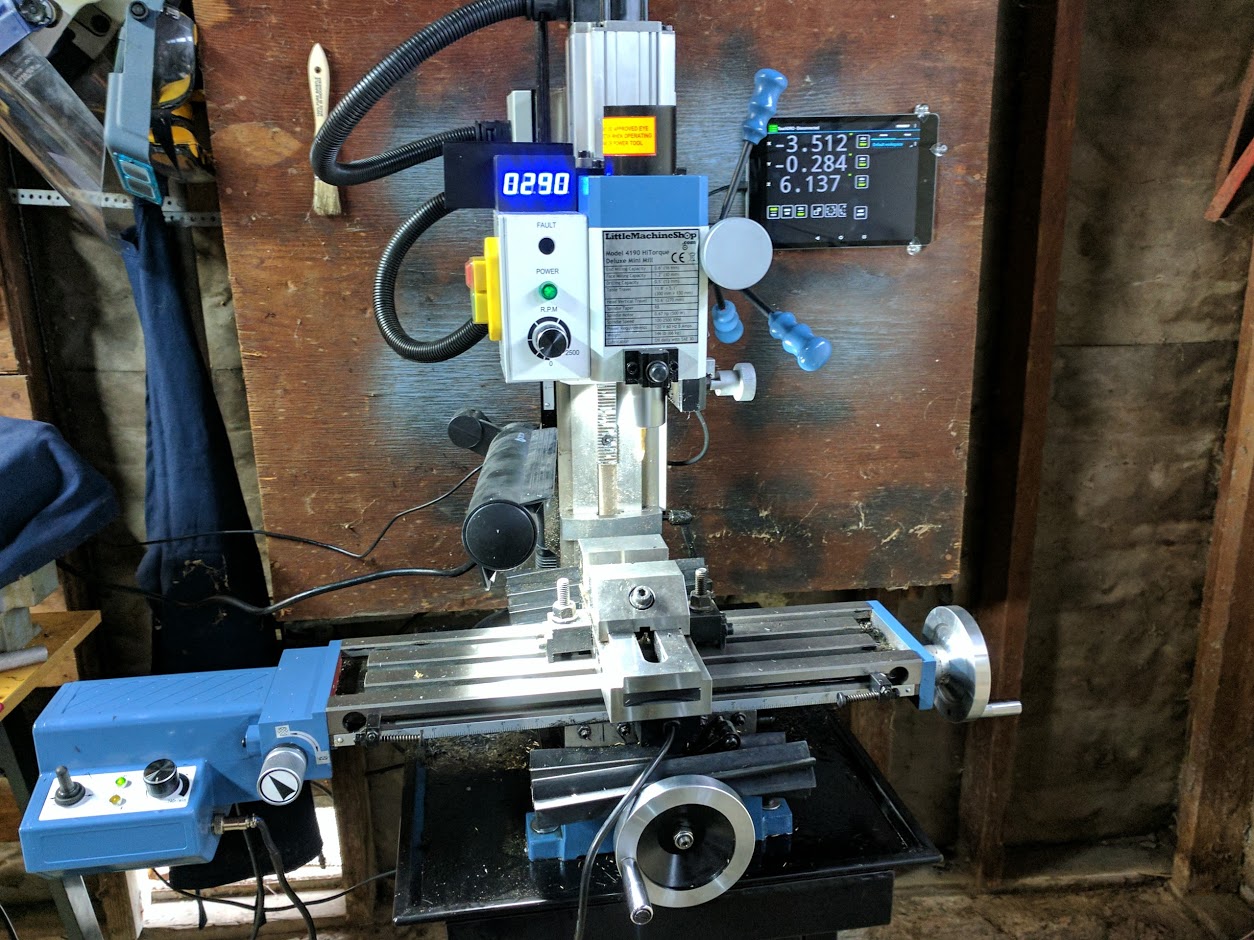
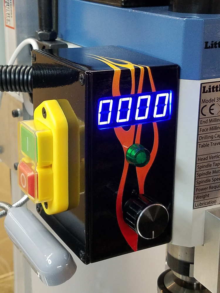
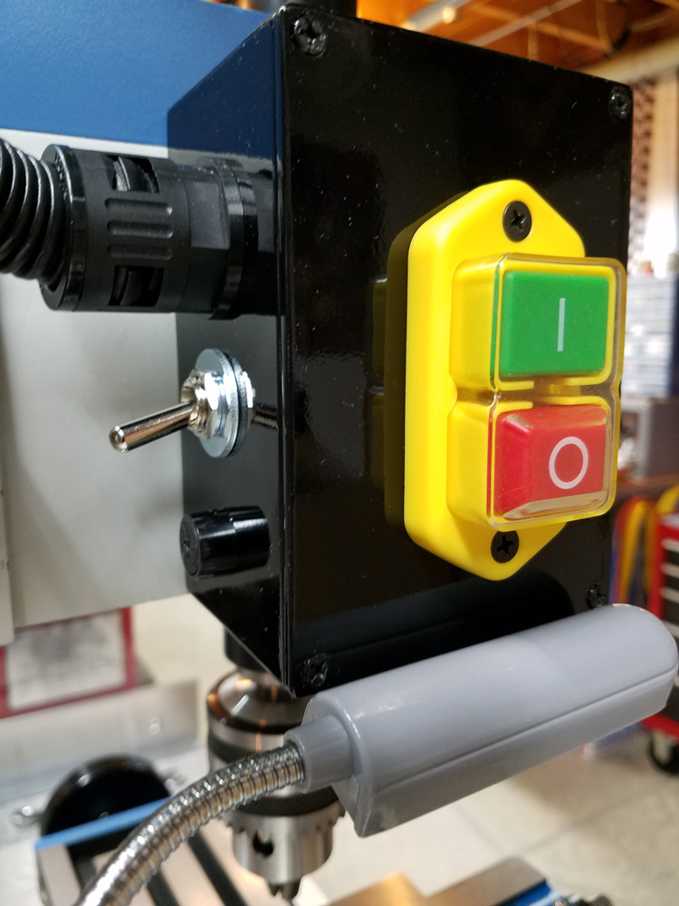
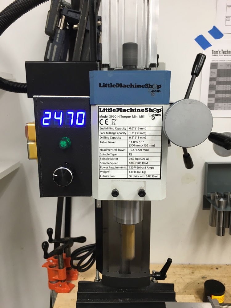
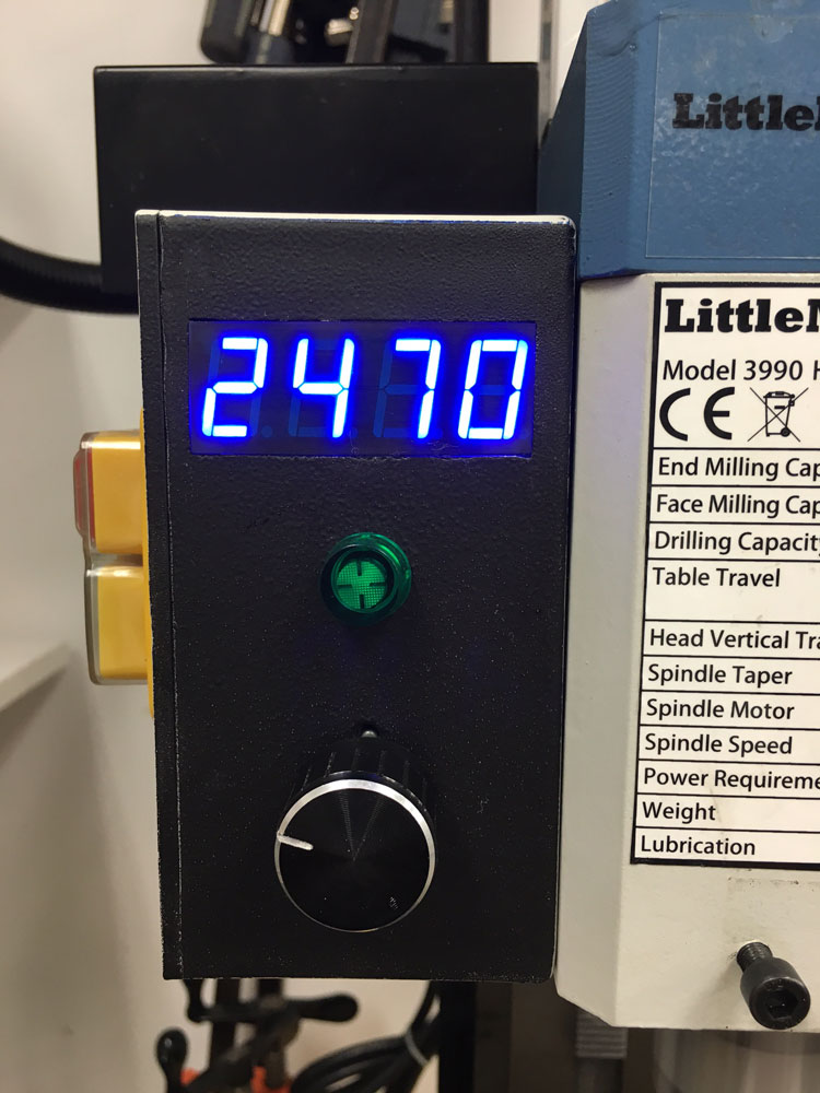
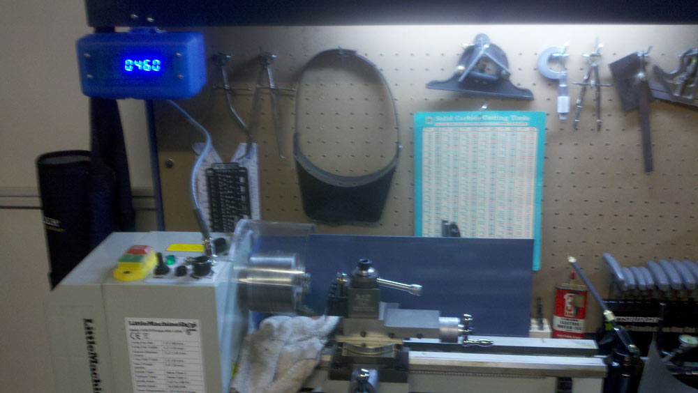
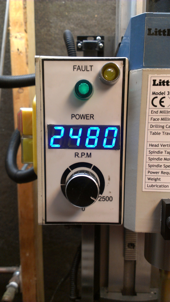
My Mill:
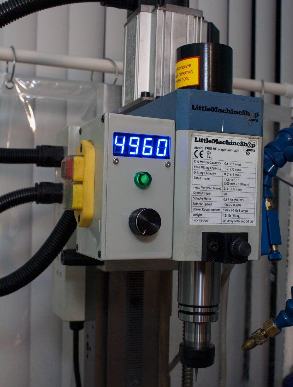
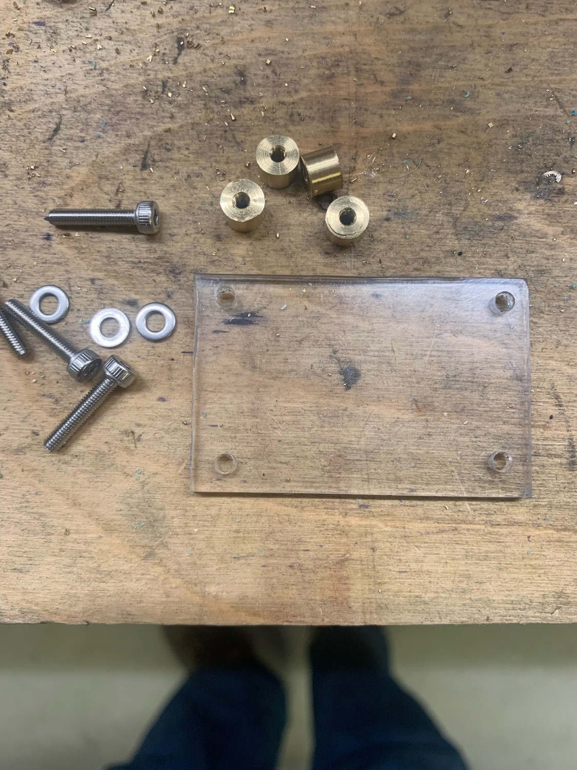
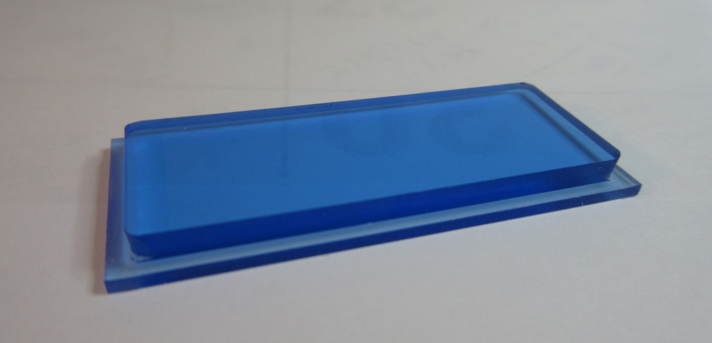
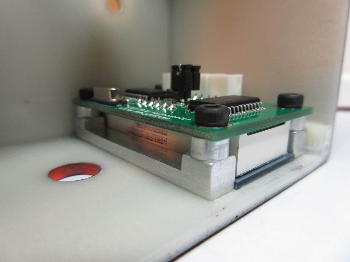
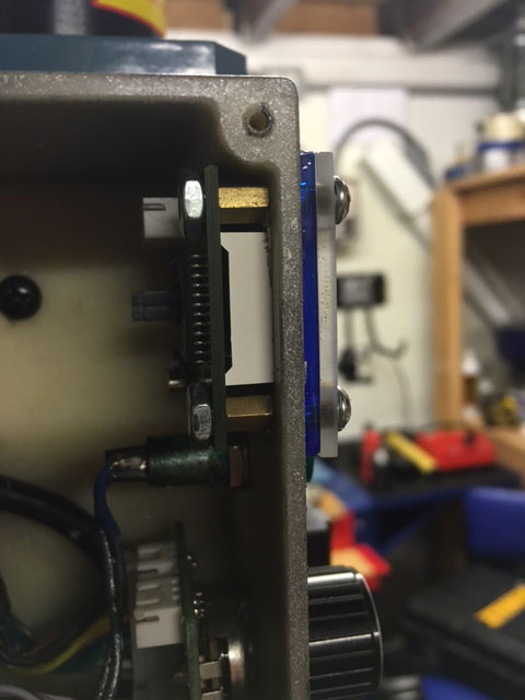
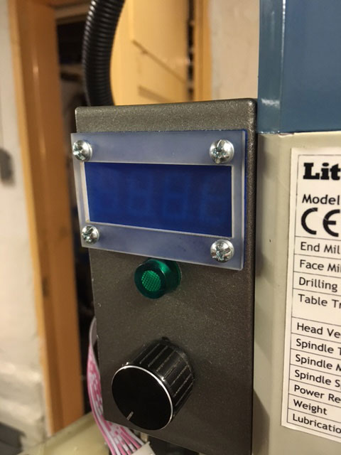
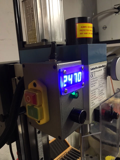
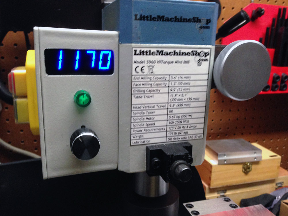
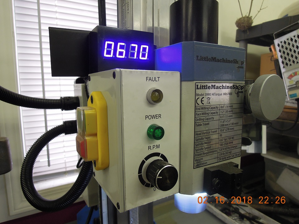
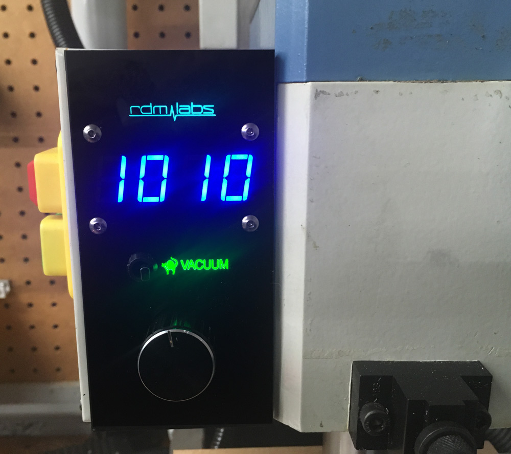
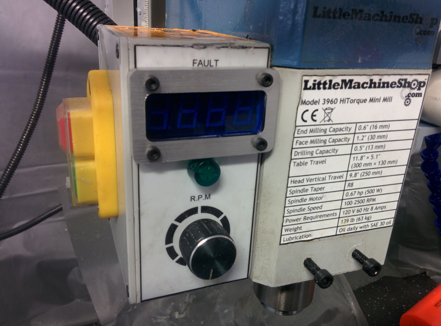
I used my CNC mill to machine out a hole in the abs control box as well as two holes appropriate for 4-40 screws. Next I purchased a sheet of 3/16" thick "2069 transparent blue cell cast acrylic" and machined portions of it down by 1/8" to form a window which sits flush with the surface of the control box. Two 4-40 lock nuts, two 3/8" 4-40 standoffs (these are the exact same height as the digits), and two 3/8" 4-40 socket cap screws plus some blue locktite were used for mounting.
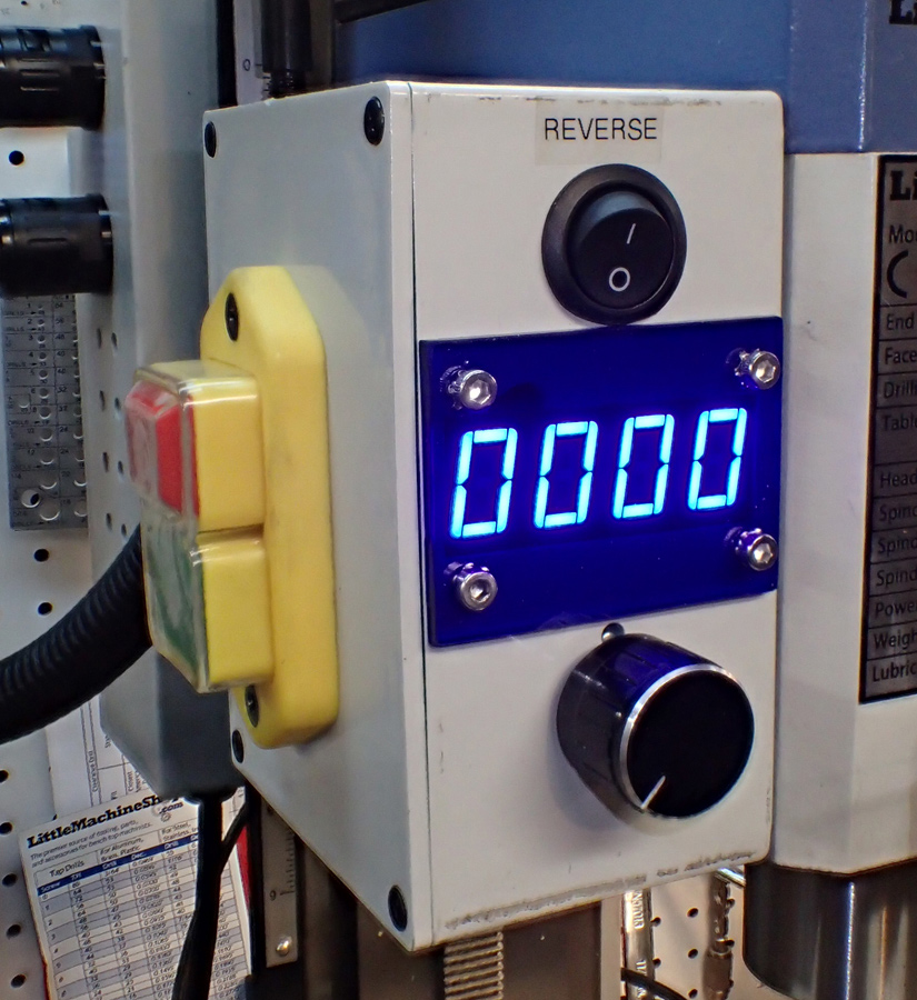
I still haven't figured out the best way to take a picture of blue LEDs. In person the display digits look even better.
Custom Enclosure Vendor - Pete from Hyper-Formance:
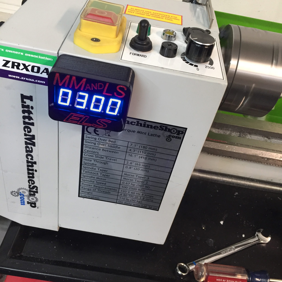
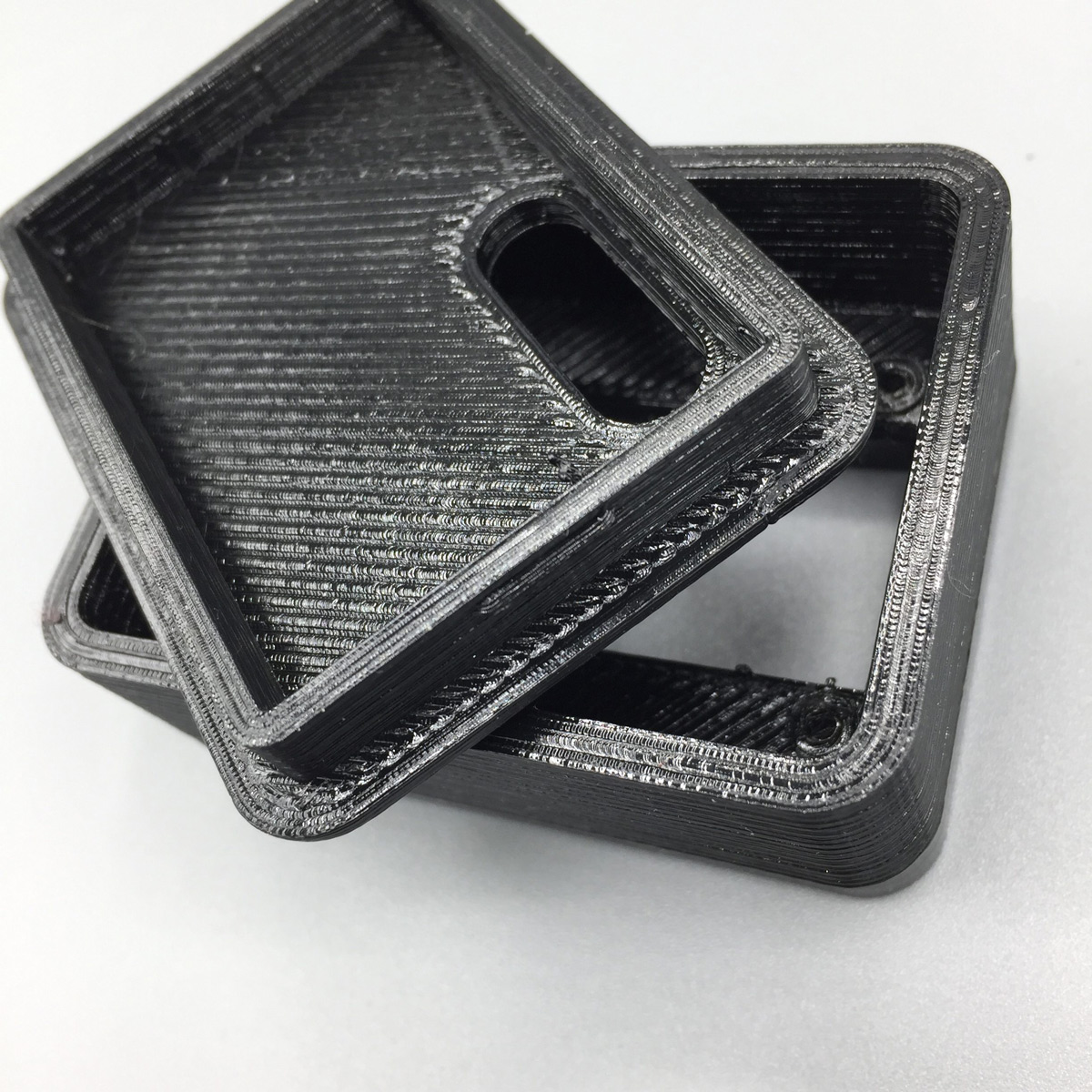
Don't want to make your own enclosure? Pete from Hyper-Formance out of Tempe, AZ is a one-man shop who makes a variety of motorcycle, mini-mill, and late tooling items. One of these items includes an enclosure for the SX2/CN2 Tachometer V2 board which can be purchased here. The base of the case is 3d-printed and the front is a piece of laser-cut acrylic which Pete can custom engrave and fill for you. You can watch a video of the kit in action on youtube. Please note the digits in person are much more visible than are show in video.
Anthony from Berkeley, CA:
Anthony installed his tachometer on his Micromark 7x16 lathe. He cut a hole in the top of the lathe control case, covered the hole with a piece of cut plexi glass and dimmed the display with a piece of "LED Dimming film" purchased from Amazon. I spy custom machined brass nuts in his build which I bet I know how he made!
Bill:
Bill tested out his new 4190 Deluxe Mini Mill by machining down and hollowing out a Delrin disc. He then mounted the tachometer guts inside of this. An excellent write up of this can be found here!
Brian:
Brian tried a spin on the reference design present on the v2 tachometer page. He cut the acrylic lens and bezel with a laser cutter then milled the bezel to seat the acrylic window. You can find pictures of their display here!
Bob from Ohio:


Bob from Ohio used machined aluminum standoffs epoxied to the inside of his mill control enclosure to affix his tacometer.
He then finished up his clean enclosure with a custom paint job!
This approach negates the need to affix the the blue acrylic window via mechanical or adhesive means and therefore allows easy swap-out.
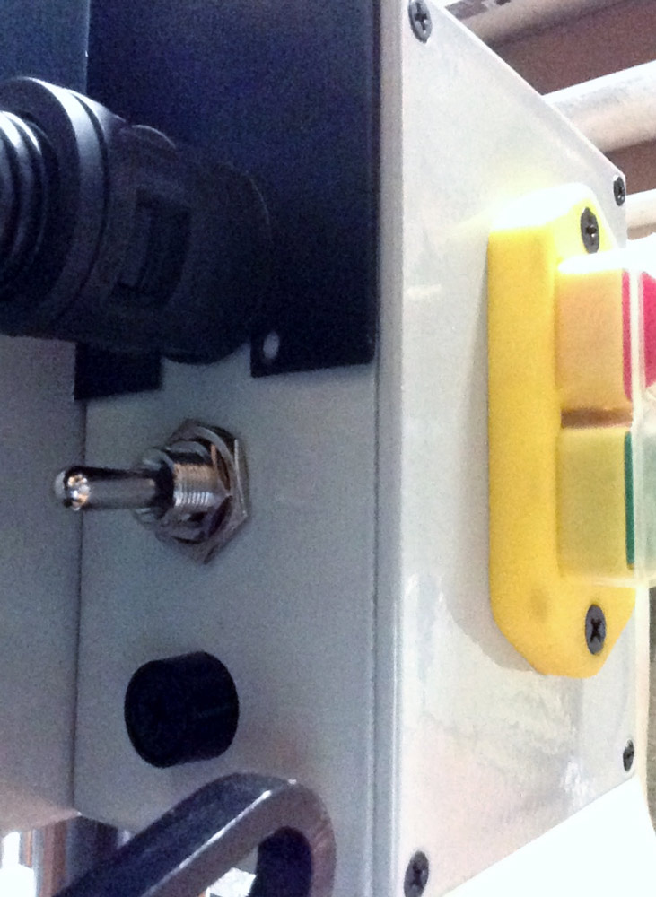
Bob also installed an SPST switch on the back of his mill control box to allow the spindle to be reverse.
With a disclamer these measurements worked for his mill but may not work for yours, Bob provided his BobCAD® drawings in the hopes others would find them useful. Thanks Bob!
Chris:

Chris is luckly enough to have access to a laser cutter at work. He used this to make a panel to hide the rough-cut hole in the cut into the control box. The translucent blue plastic was sourced from a 1$ Walmart clipboard. The translucent white bezel is clear plexiglass from Lowes which has been sanded. To affix the V2 tachometer to the inside of the control box he used 4 4-40 standoffs, nuts, and bolts.
I think this came out pretty sharp and negates the need for any 2.5d milling. If you would like to copy this look but don't have a laser cutter, try searching your area for a local hackerspace. Many have one nowadays and will be happy to help you use it.
Craig from Lone Tree Colorado:

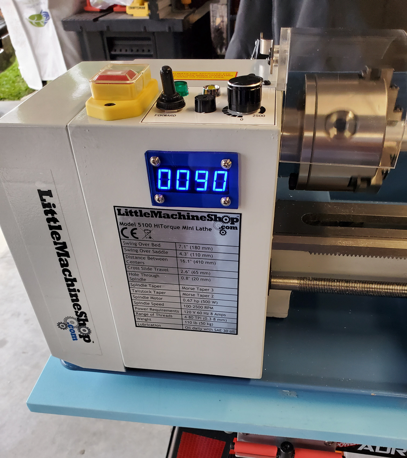
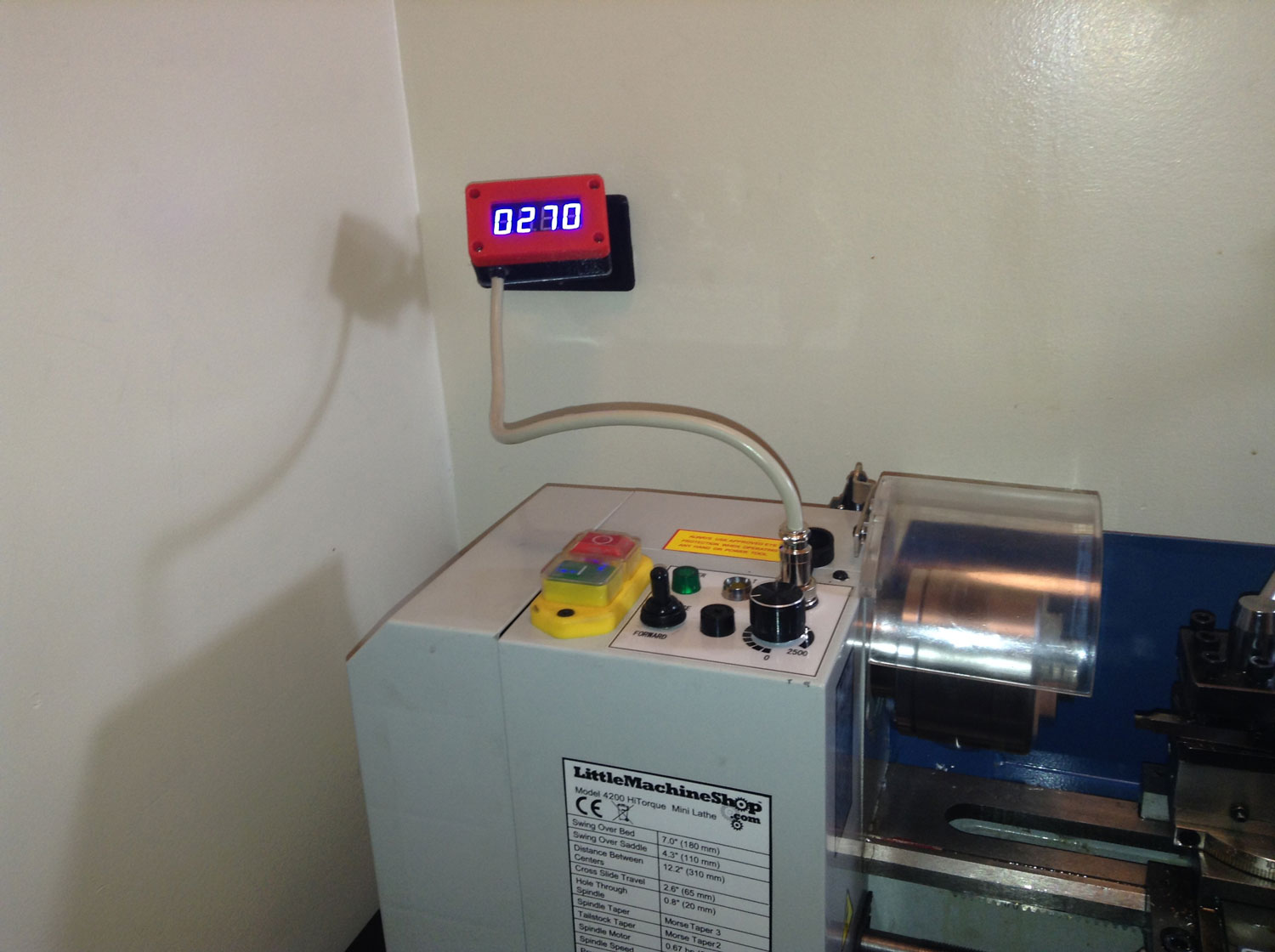
Craig mounted his tachometer on his LMS510 Mini-Late in place of where the normal external tachometer port is located. A great improvement if I may comment! He plans to place a piece of plastic atop of the screen next.
Doug from Princeton, NJ:
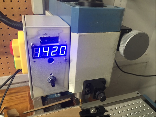
Doug drilled and tapped 4 holes in a piece of blue plexiglass which he then glued inside of his mill control box. The tapped holes allowed for the tachometer to then be mounted easily using 4-40 hardware. Doug also added a forwards/reverse switch to his mill on the side.
Drew:
Drew grabbed a blue plastic clipboard from Walmart and used this to make the tachometer display cover. The plastic was originally clear so he used 2000 grit and a buffing to achieve the smoked plastic look. Drew affixed his tachometer from the inside which results in a very clean look!
Fred from Florida:
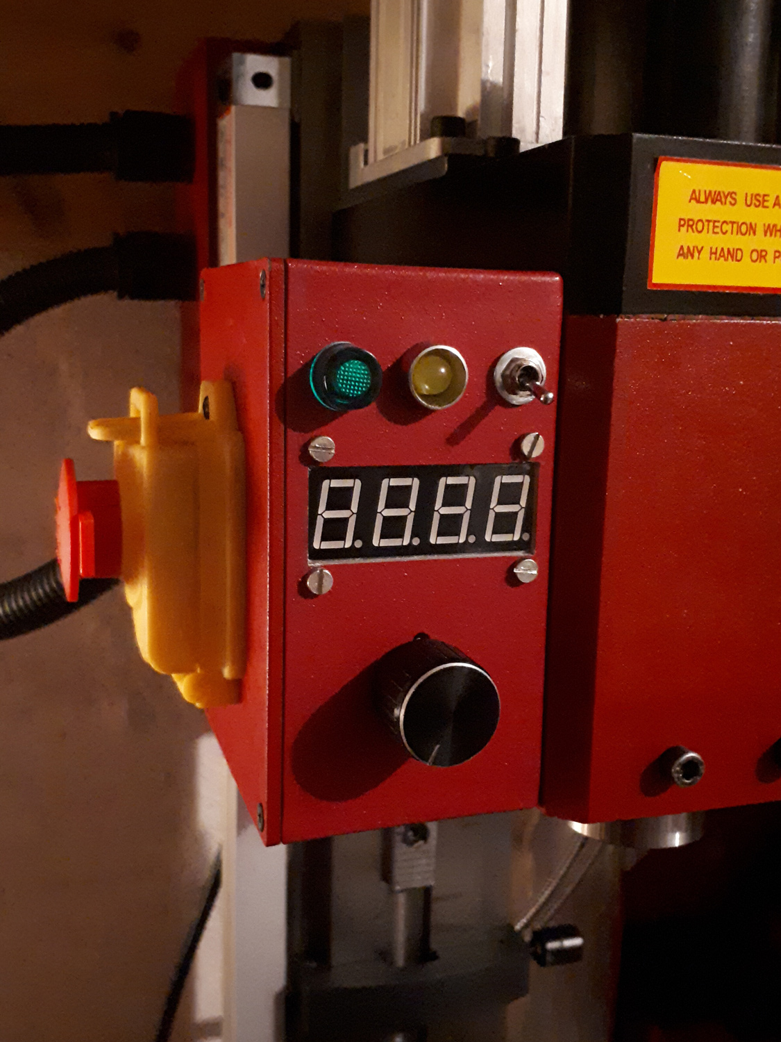
Fred mounted his tachometer inside the control panel and elected to replace the power-on light with a reverse switch. In addition he made a block/holder for the spindle lock pin and used the two protection shield bolts to affix adjustable led worklights.
George from California:
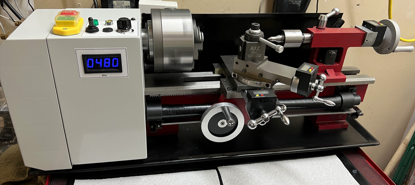
George installed his tachometer on his late and used a translucent blue acrylic cover to keep dust out. Simple and effective.
Greg from Colorado Springs:
Greg who has experience building large scale RC Airplanes installed tachometers on both his lathe and mill which came out very clean!
He has offered to answer questions for anyone who wants to attempt a similar install.
Greg cautions that his install method was a labor of fun vs time expediency.
I personally do not own a lathe and appreciate the internal shots. As you can see it is more involved than the install of these displays in mini mills.


To start Greg used yellow tape to mark out the boundaries of the internal cavity of the control box.
As a word of caution Greg stressed the importance of ensuring the display hole position allows for the tachometer pcb to fit within the insides of the case.
He then used a 1/4" dremel sanding drum to rough the display hole before cleaning it up with a sanding stick and exacto knife for the corners.
With the hole cut/test fitted, Greg used a bit of epoxy mixed with fiberglass to affix tapped-nylon standoffs inside the case by mixing fiberglass/epoxy together.
(I like this approach!)
The display cover is made of 3/16" 2069 cast acrylic whose sides were milled down to under 1/8" to allow for a little under 1/16" overhang and 1/16" insertion depth.
Greg used 320, 400, and 600 grit sandpaper to bring the machined edges back to a smooth and clear finish.
After ensuring a tight fit, greg used RC canopy glue to affix it to the control box
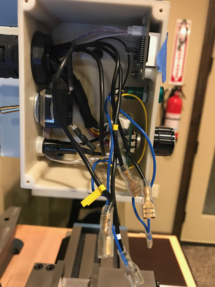
From the wiring pictures it is clear there is not much space inside the lathe control box. If you choose to attempt this route please ensure you keep the low voltage and high voltage circuitry as isolated and far away as possible!
Greg used a similar approach with the mill. His tolerances were close enough that the display cover snapped into the hole he cut which is impressive!
To keep the display high up in the case he only epoxied two standoffs and used a bit of hot glue to affix the top of the tachometer pcb to the control box enclosure.
He cautions that the tachometer unit is compact thus a little planning to ensure the tachometer does not interfere with the power switch is worth the upfront effort.
While in the control box Greg removed the 7-pin port plug and did a tidy job installing a forwards/reverse switch too.
Iven:
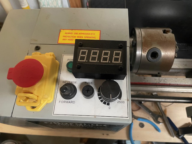
Iven epoxied his V2 tachometer behind a piece of smoked blue plexiglass to make the digits really stand out. Since he wasn't using the 7-pin din port for an external tachometer anymore he removed the cable and replaced it with a spindle forwards/reverse switch.
Jim:

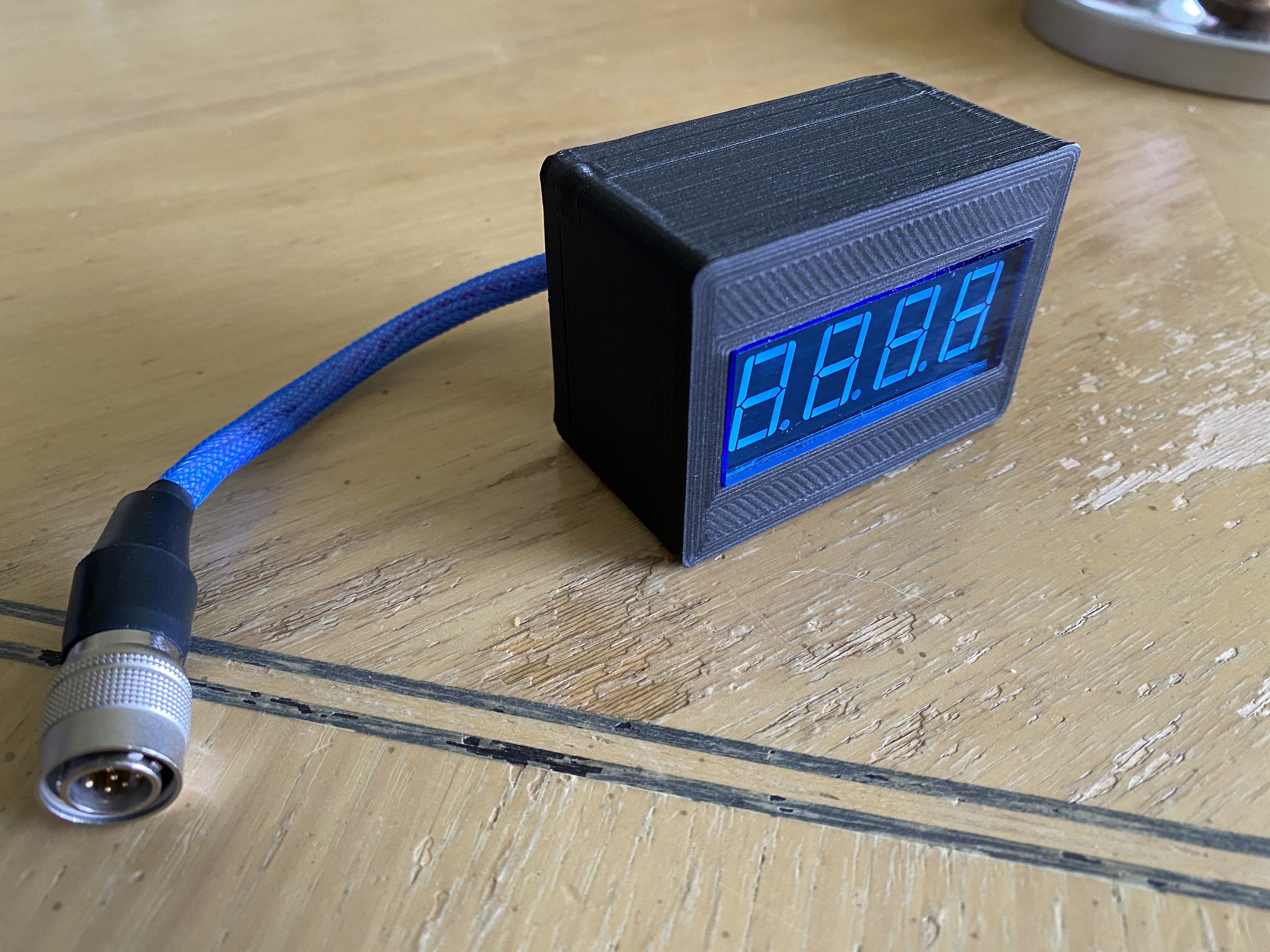
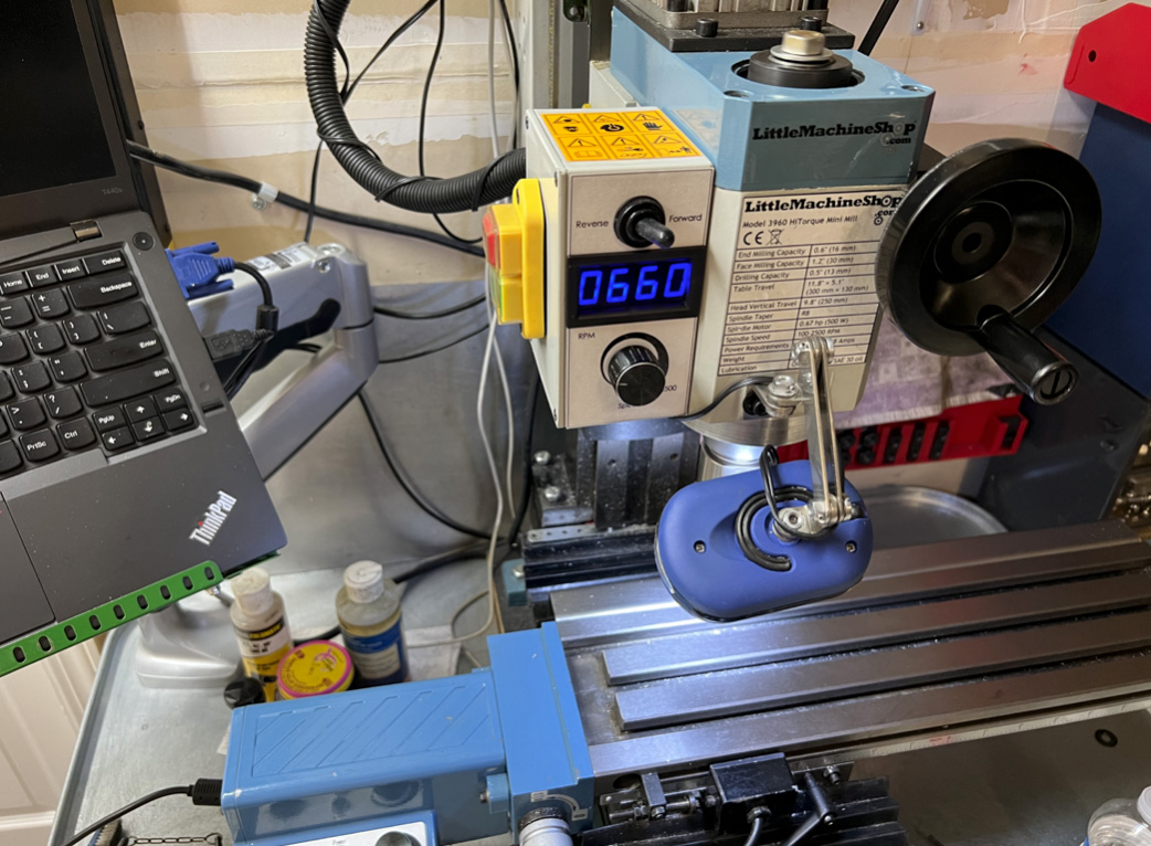
Jim installed their tachometer in a plastic enclosure from Amazon and affixed it with magnets to the stock mounting plate that comes on newer mills. To avoid drilling holes he made his own 7-pin DIN cable!
Jiptech:
Jiptech 3d-printed their magnetically attached enclosure using Carbon-fiber infused PETG with heated fastener inserts. Instead of using the standard XLR barrel connector, they installed/used 10-pin hirose connector components. They also machined the stock tachometer bracket down to size to make for an overall very clean machine!
Juan from VA:
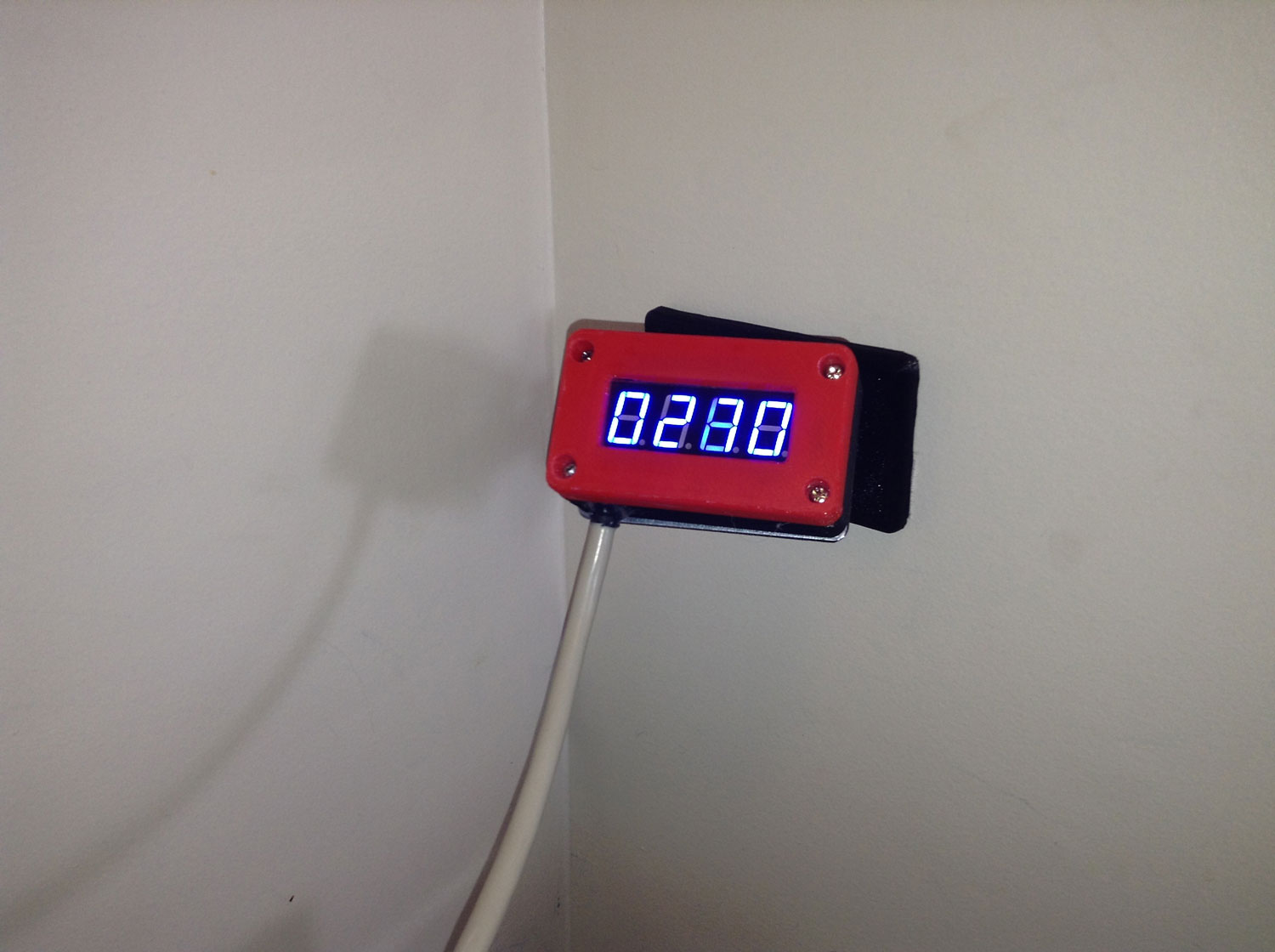
Juan wanted to mount their tachometer on their lathe but in a manner that didn't cause any permanent changes to the machine enclosure. He came up with a novel 3d-printed enclosure that allows the data cable to be passed through the existing data port hole and affixed using one of the machine's cover screws. As you can see he also angled the tachometer display which should make reading it even easier. Juan has offered the stl files he used to make this enclosure which can be downloaded here:
juan_from_va_tachometer_case.stl
juan_from_va_tachometer_case_door_w_ear.stl
Kelly:
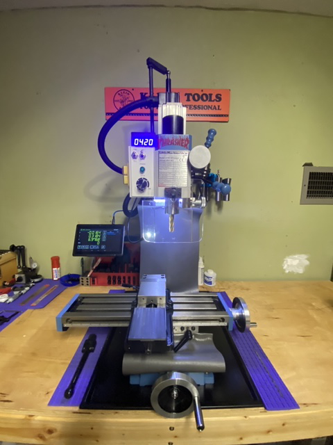
Kelly cleanly mounted their tachometer kit in a separate enclosure that sits atop of the standard control box assembly. A full writeup of the proccess is available on their blog!
Kurt:

Kurt has made several modifications to his mill to include a custom-milled spindle lock, metal handle knobs to replace the plastic z-axis course feed knobs, a forwards/reverse spindle direction switch, and tachometer.
To obtain the sharp square edges around the display Kurt used a fein tool and to tie everything together he designed and had a friend print out a custom faceplate sticker.
Lee from VA:
Lee from VA mounted his tacometer atop of his late. Lee mentioned they thought this made installation easier.
Matt:
Matt installed his tachometer in the stock enclosure on his lathe. He kindly provided me this picture of it before they had a chance of installing an acrylic front plate.
Mike:
Mike installed one tachometer kit on his mill and another on his lathe. While he had plastic on-hand for his install he mentioned he liked Chris's use of a blue clipboard as a source of plastic!
Phil from San Jose CA:
Phil has both a cleanly upgraded/designed mill and lathe that he integrated tachometers kits into. In order to facilitate easy replacment of lenses he used display bezels and lenses sourceable from Digikey (Also a great way to allow some potential wiggle room when cutting holes in the machine enclosures!). Phil has provided a PDF writeup that is worth a read, a 3d pdf, and last but not least a solidwork model of the standoff in case it is useful to others. Thanks Phil!
PDF Writeup
3D PDF Model
Solidworks Standoff Model
Randy:
Randy made an exceptionally clean looking front panel by spray-painting a piece of 0.125" translucent gray acrylic using Rust-Oleum Black Satin paint. He then laser-engraved a (reversed) image of his lettering/logos to allow the led light to show through. A local hackerspace has a laser engraver and I will definitely be trying this novel idea out next time I need to make a display control panel!
Rick:

Rick designed and 3d-printed an enclosure for his tacometer that sits atop the standard control box. He was also kind enough to share his design on Thingaverse. Thanks Rick!
Richard from TX:
Richard used a 1/4" sheet of blue plexiglass purchased from Amazon to cover his tachometer display. He also made a new front-panel sticker by printing on a packing slip label
and then using packing tape to protect it/give it a clean look!
Robert from Pittsburg, PA:
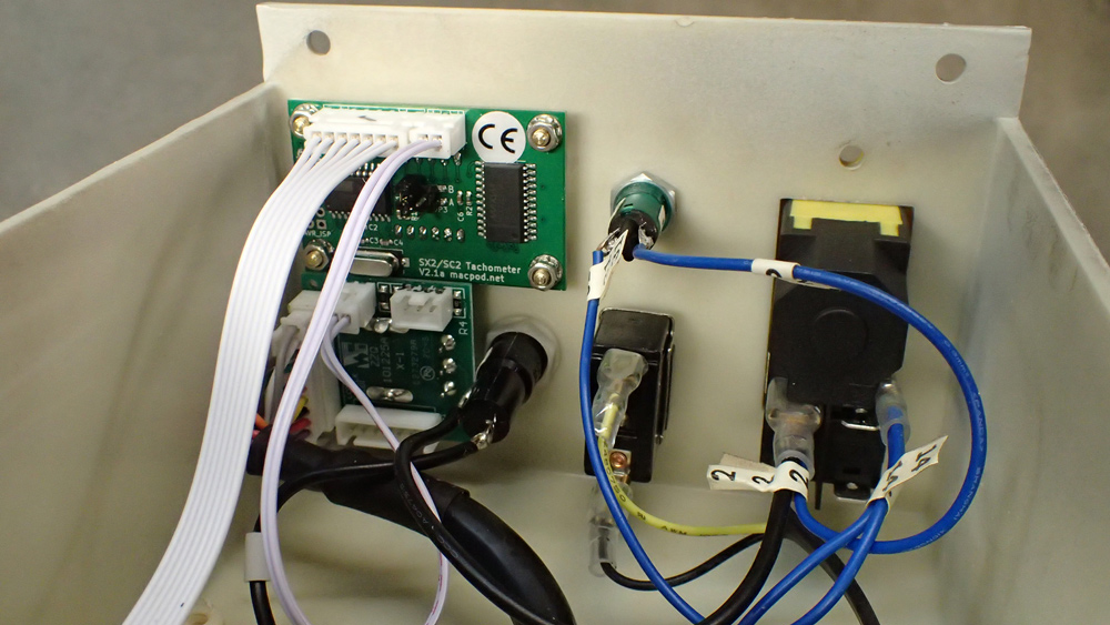


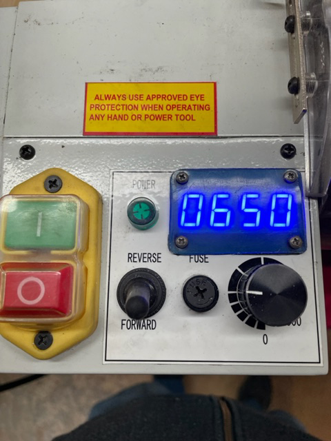
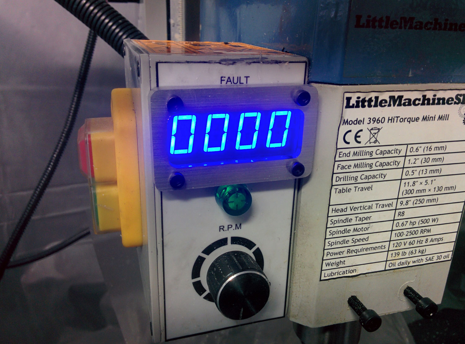
Robert from Pittsburg, PA not only installed his tachometer on his lathe in record time but was kind enough to send the following instructions/images for others to follow. Thank you Robert! The lathe installation is a bit tricker than the mill installations.
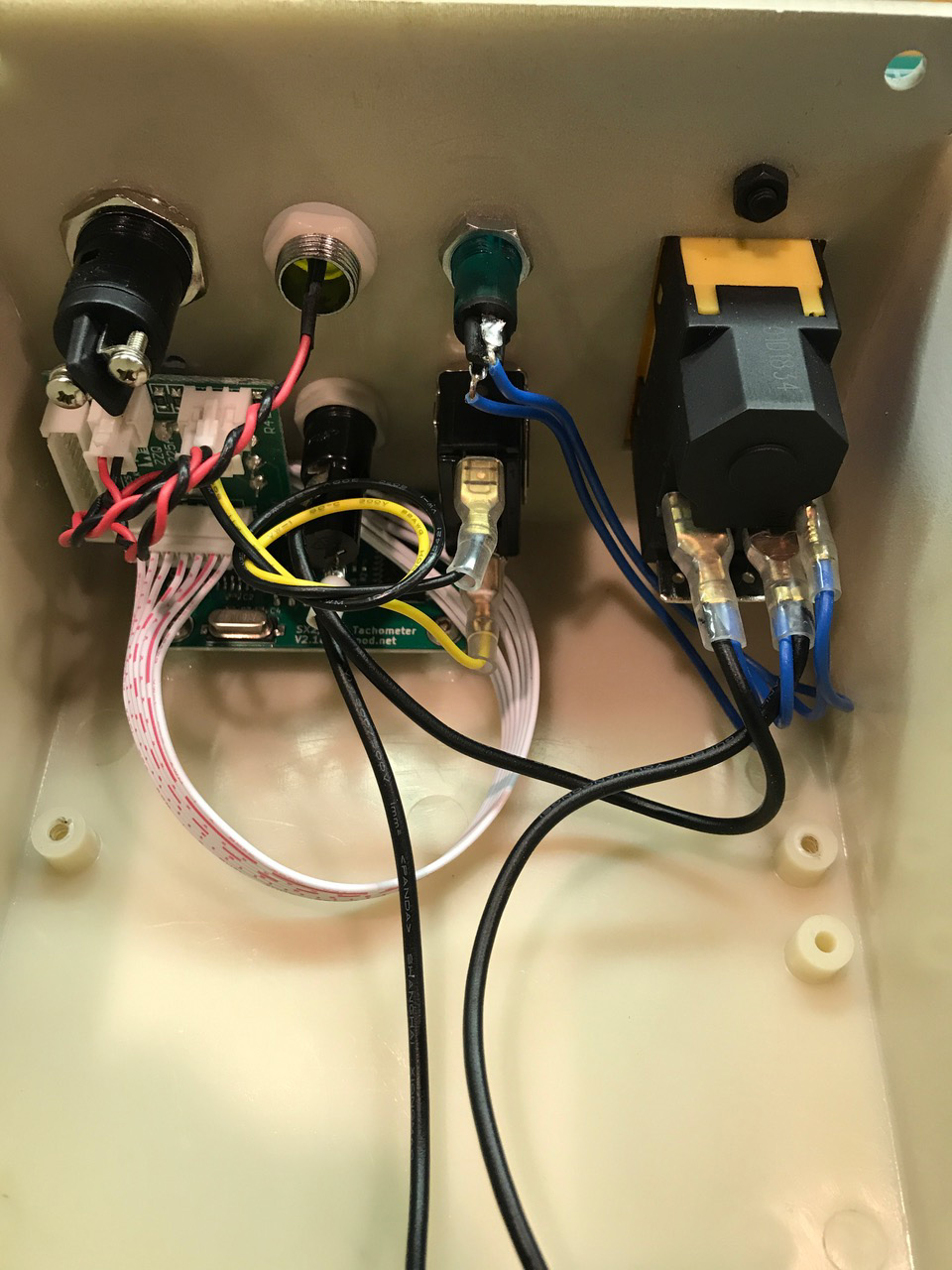
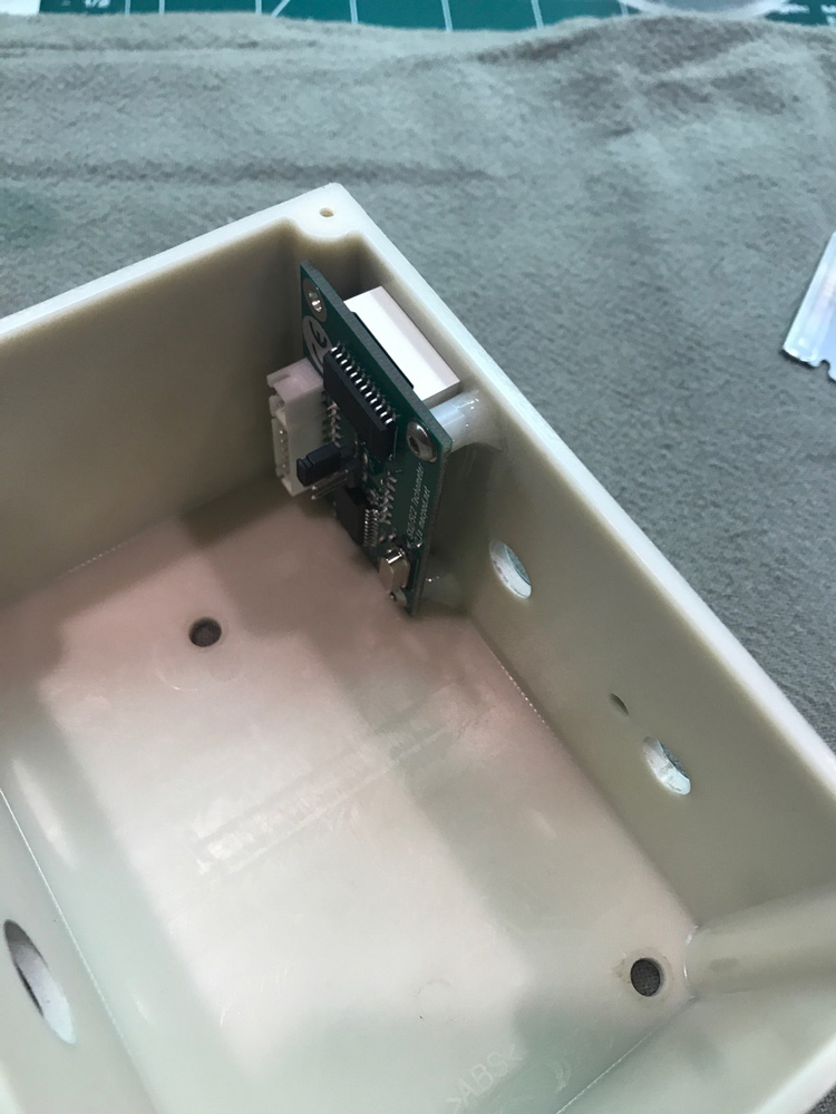
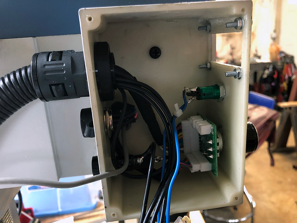
1. The wires to the main controller board are labeled, but before disassembly I used additional wire labels to identify where all the other wires were connected, and took photographs of the inside of the enclosure to to refer to if needed to guide reassembly.
2. I removed all of the switches, lights, fuse and potentiometer from the enclosure before cutting the opening for the display, I unsoldered the two wires to the power light, and cut the white header connector off the now unused original tachometer cable.
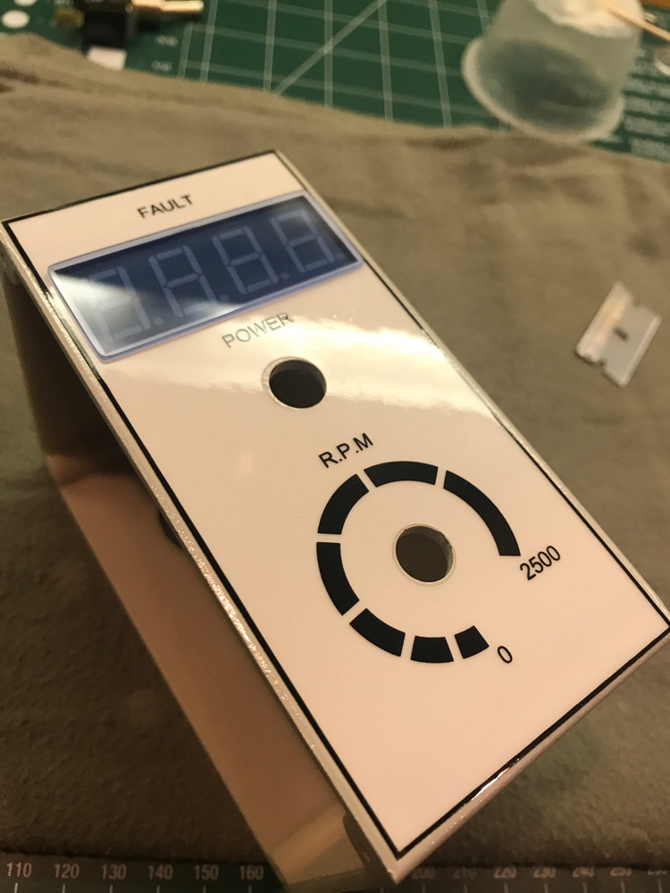
3. I removed the factory installed white paper control panel label, you really don't need a label to tell you where the fuse or power pilot light is. I used a P-Touch label maker to only make labels for forward and reverse directions. I like the cleaner look.
4. I downloaded the dxf template file of the circuit board, imported it into Corel Draw, printed it on a removable shipping label, then stuck the label to the outside of the enclosure as a cutting guide to make the hole for the display.
5. With a Dremel tool I cut right through the paper label to make the the rough opening for the display. I used a fiberglass-reinforced cut-off wheel disk that was labeled for cutting plastic, then finalized and fine-tuned the opening to exact size with a file.
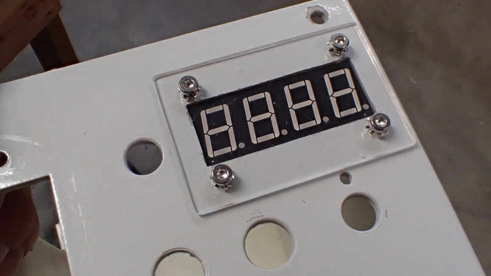
6. I inserted the display board backwards from the outside of the enclosure to act as a guide for where to drill the mounting holes.
7. I used metric brass standoffs to mount the circuit board, they were 5mm tall and had M3 threads, I used M3 X 5mm round-head screws to attach the circuit board to the standoffs, M3 X 10mm socket head screws were used to attach the plexiglass cover, outside tooth lock washers were used in all eight places.
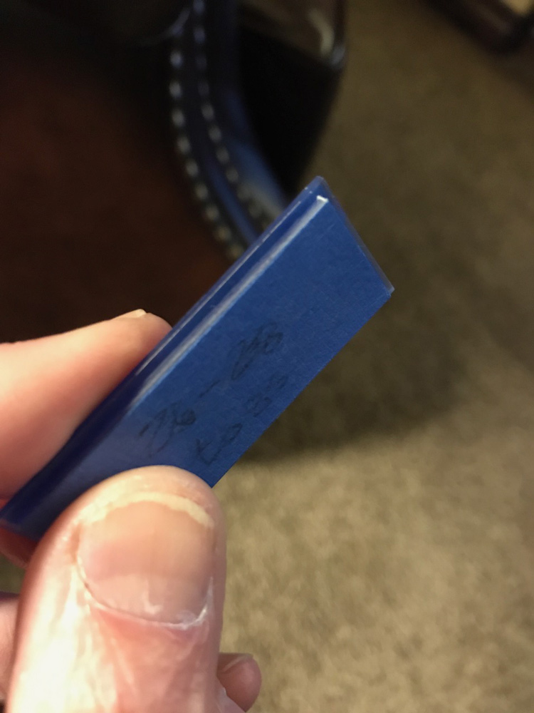
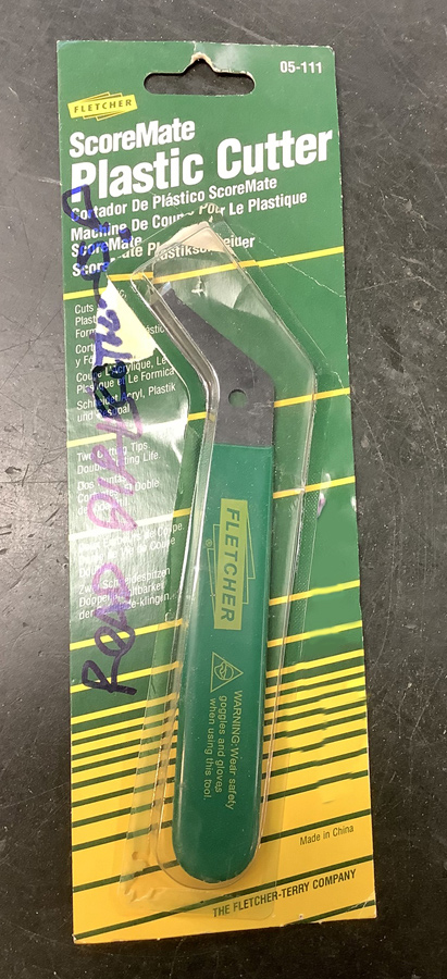
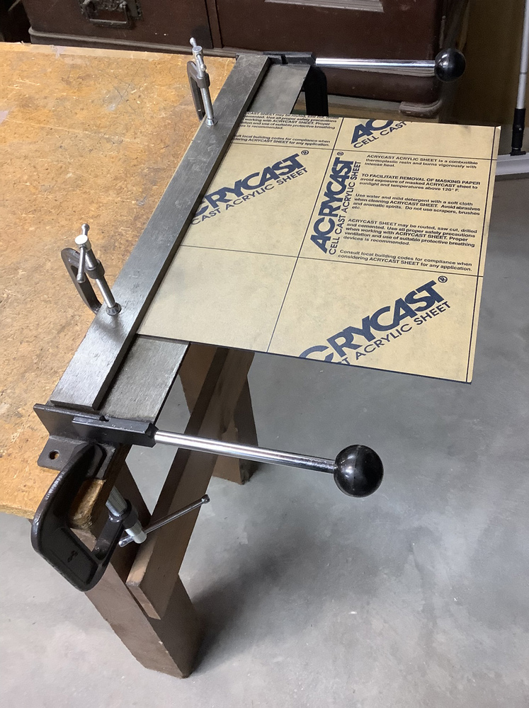
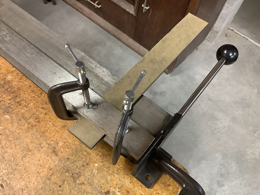
8. I cut a cover from scrap 1/8 inch thick clear Plexiglass using a plastic scoring/cutting tool, smoothed the edges with a file and sandpaper then polished it with a buffing wheel in my drill press. With the clear plastic cover the display was distractingly bright, so I purchased some 1/8-inch transparent dark blue Acrylic from Amazon (Search for "Cast Acrylic Sheet - .118" Thick, TP Dark Blue, 12" x 12" Nominal") and made a new cover which was much more pleasing to the eye.
9. I used a bending brake from Harbor Freight to snap the plastic after it was scored, this was overkill because you can easily and accurately break the plastic along the score line by bending it over the edge of a table, but it made me feel good to get some use out my long-neglected bending brake.
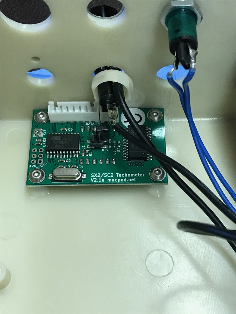
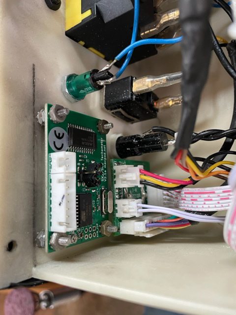
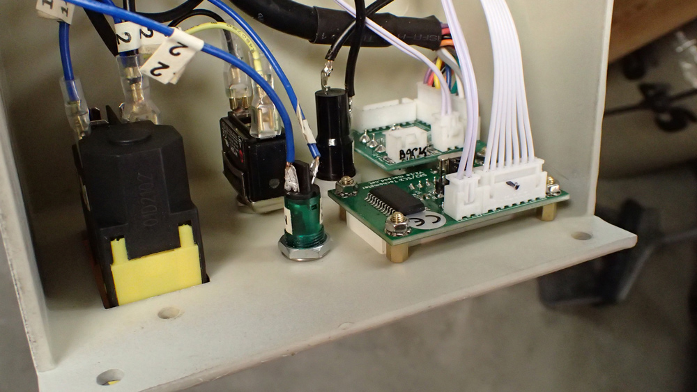
10. I had to bend back the retaining clip of the white two-prong socket on the potentiometer board in order to insert the 2-pin JST XH fault cable plug.
11. In fact, the green power pilot light is redundant and could actually be eliminated, as the tachometer display lights up when power is applied and goes dark when power is disconnected.
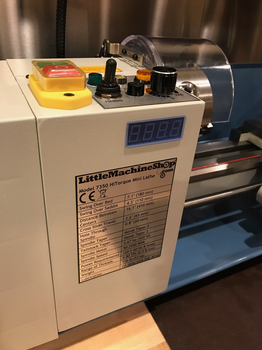
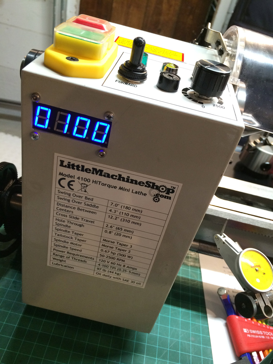
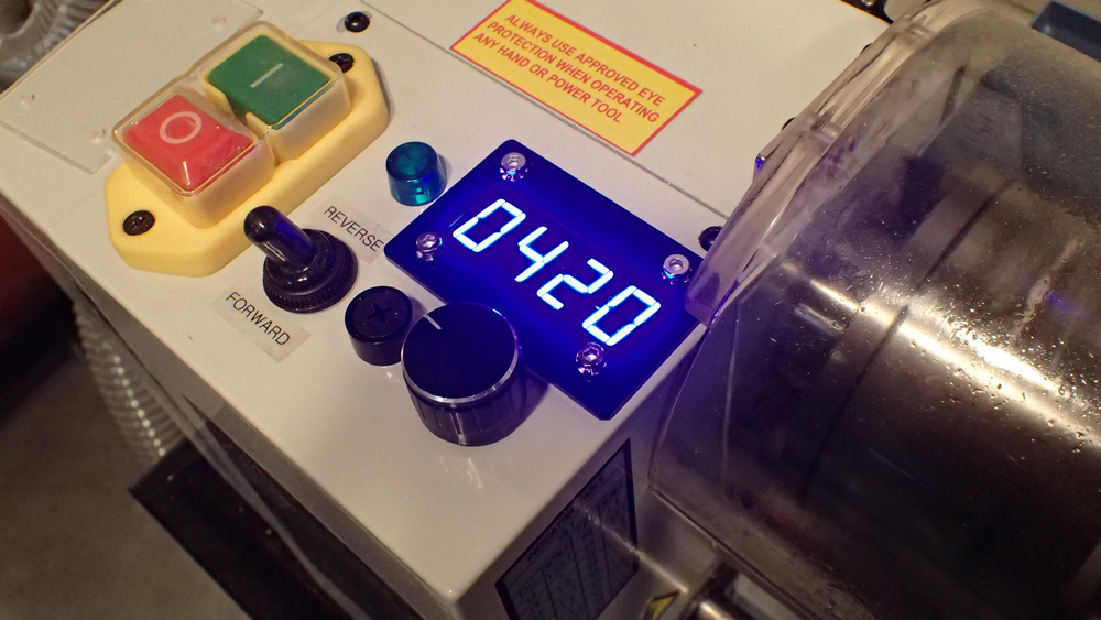
12. The transparent chuck guard is lifted up 1/8th of an inch by the blue display cover, but this does not interfere with the fail-safe operation of the chuck guard. I could cut back the blue plastic a quarter-inch to avoid this, but have chosen not to.
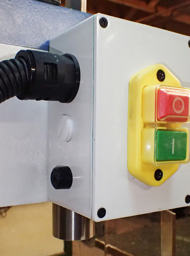
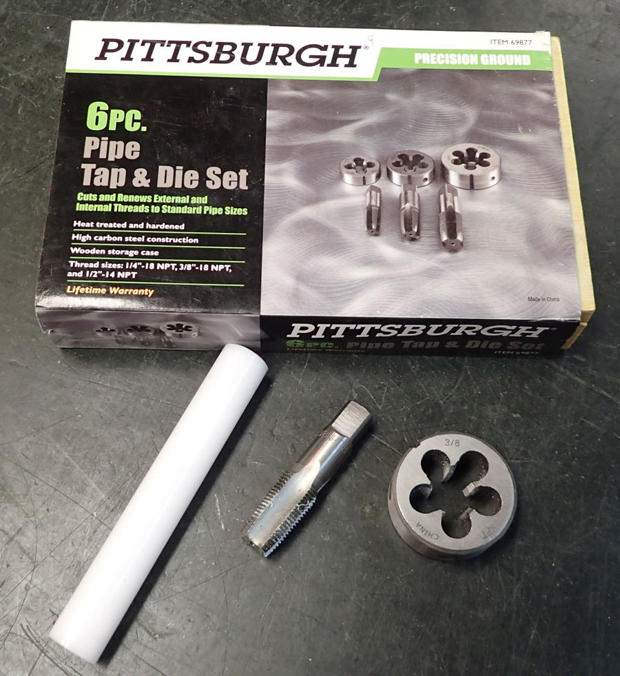
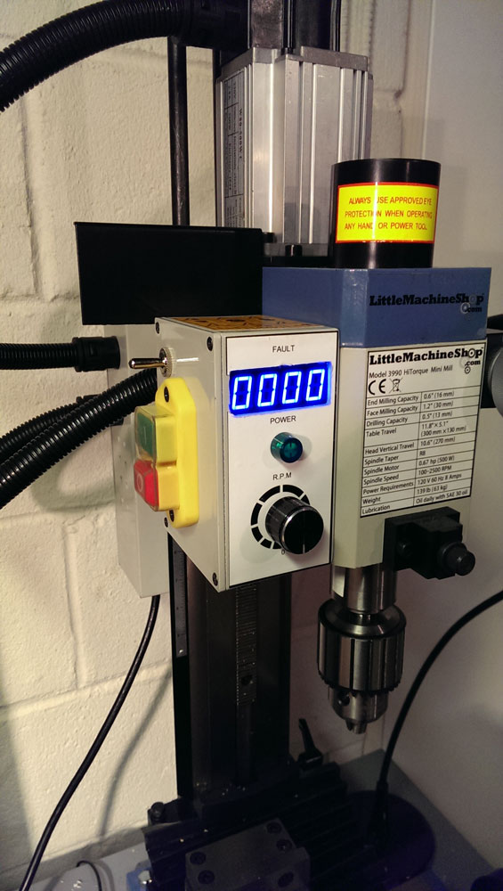
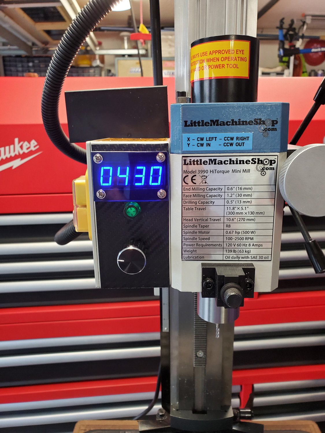
Robert also intalled a tachometer (and reverse switch) on his mill. He choose to install the reverse switch on the front for visibility/access. To plug the hole in the rear of the control box Robert tapped the hole with a 3/8" NPT tap then screwed in a matching threaded plastic rod into the hole.
Satisfied Customer:

This satisfied customer who wishes to remain anonymous cut a clean rectangular hole in his mill's control box and mounted the tachometer without a cover. They did not have any standard size nuts/bolts on hand but did want to comment that m3x.5 bolts will work in a pinch too!
Spencer C.:
Spencer converted his manual mill to a CNC mill using CNCFusion's SX2 Kit. He then whipped this faceplate up with some spare 1/4" aluminum plating, 1/8" plexiglass, and some blue vinyl tinting they had lying around.
Steve from SMG Fabrications:
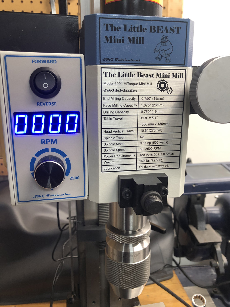
Steve installed both a tachometer and spindle direction switch in the control box of his mill. To finish it off he replaced the front decals with some clean/professional custom decals.
Tio from Fort Lauderdale:
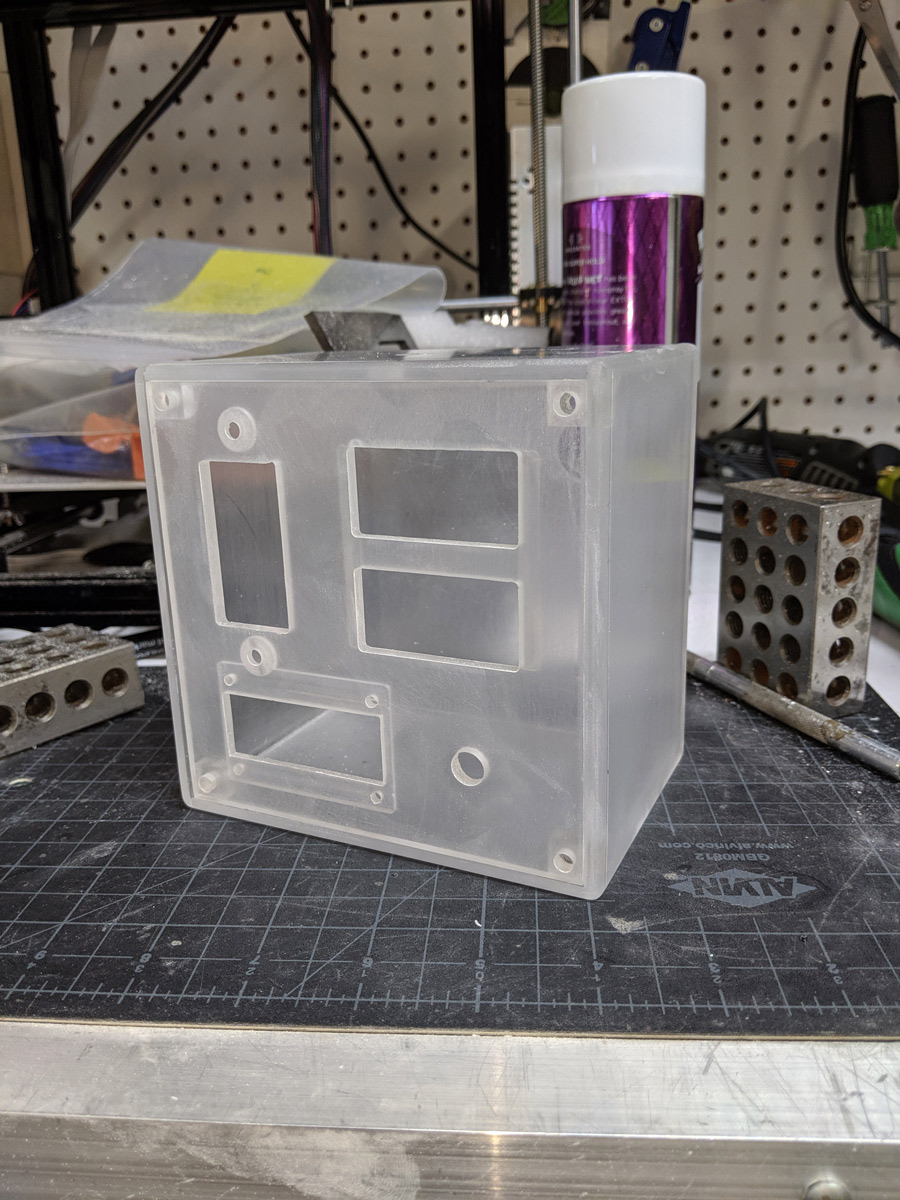
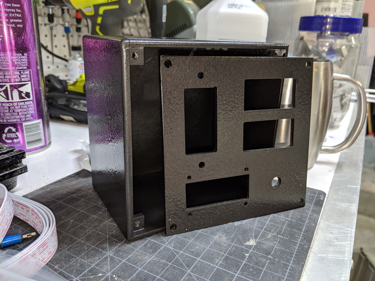
Tio decided adding the tachometer alone wasn't enough for his mill and used Fusion 360 to design a whole new control box!
The new box relocates the power switch, adds a forwards/reverse switch, and includes a light switch too. The enclosure which is made out of cast acrylic also houses the spindle ring light power supply.
For the finishing touch Tio used Krylon Hammered Black spray paint to give the control box a really nice appearance.
Tom from Norway:
Tom drew inspiration from Kurt's setup and used his DRO machine setup to mill out the tachometer display pocket and screw holes.
By chance he happened to have some old standoffs in a jar which allowed the display to not completely be recessed within the case.
Tom wanted to mention he purchased a second control enclosure and other Sieg components from Arc Euro Trade (https://arceurotrade.co.uk).
He hopes this information may help those in Europe save on transportation costs incurred from USA sellers.
Vlad:
Vlad has the honor of being the first person to make a faceplate using a 3d-printer! I really like how the beveled front edge came out.
Wout from Delft, The Netherlands:

Wout crafted two tachometer cables and external enclosures to mount his tachometers on his very clean mill and lathe setups!
Zogbaker:

Zogbaker added a tachometer to his already impressive mill setup (which includes a way oiler!) and lathe using the basic template design. Instead of acrylic, he used a piece of 1x2" pre-cut borosilicate glass from Mcmaster. The gold 3mm countersunk washers add a nice visual touch!
V1 Enclosures:
Here are some clever enclosures folks have made for the V1 tachometer kit. For those who are preparing to make their own enclosures, the following dxf file of the board and hole positions may be useful:
sx2_cn2_tachometer_v1.dxf
Frank Hoose:
Frank of mini-lathe.com did a review of the SX2/CN2 tachometer. He also shows how he built a tachometer case for his lathe. It looks like it's part of the machine!
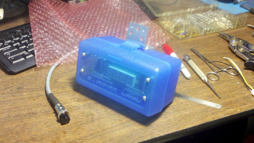
Colin:

Colin used a translucent blue Hammond box for their enclosure. This should really make the RPM digits stand out.
Mr. T:


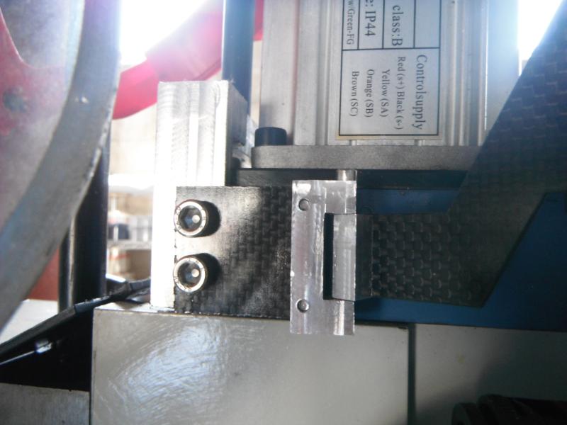
Mr T. wanted an industrial look for his tachometer enclosure and came up with this carbon-fiber setup. He came up with a very cool hinge idea too!
Mark B. from Spring, Texas:
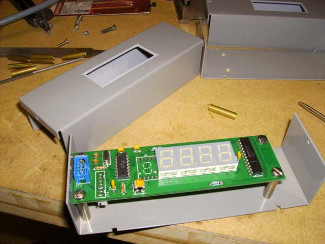
Mark B. found some enclosures at Frys (LMB Heeger LMB#650 - width 2-1/8, length 6-1/2, height 1-5/8) that were painted the same color as his machines. To cut out the display windows he used a nibbler and to make the digits stand out, he cut out sections of some inexpensive plastic boxes.
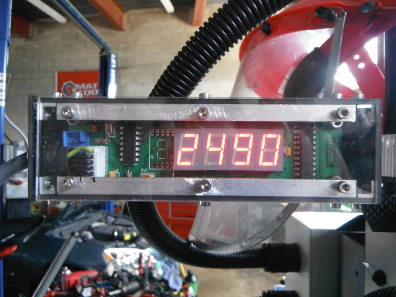
Eric of Rhema Machine Shop/WhiteStone USA:

Even made enclosures for their Lathe and Mill tachometers using a .308 cal ammo box and rifle ammo box (Case-Guard M/N-RM-50; 50 RND Rifle Flip Top; RM-50-24) respectively. Both enclosures can be had for under 3$!
Matt:
Matt took a completely different enclosure approach by mounting the 7-segment modules on a daughterboard and installing it in the mill speed/power control box. The result is something that looks factory made!
He suggested that I make a new kit to make this mod easier and now one is available!