Wiring:
The following explains how to electrically connect a Twostep board to different peripherals.
Electronics - Twostep - Wiring
Twostep Connector Overview:
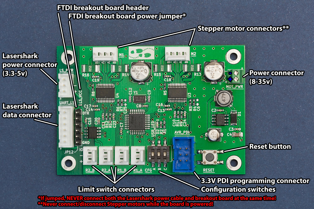
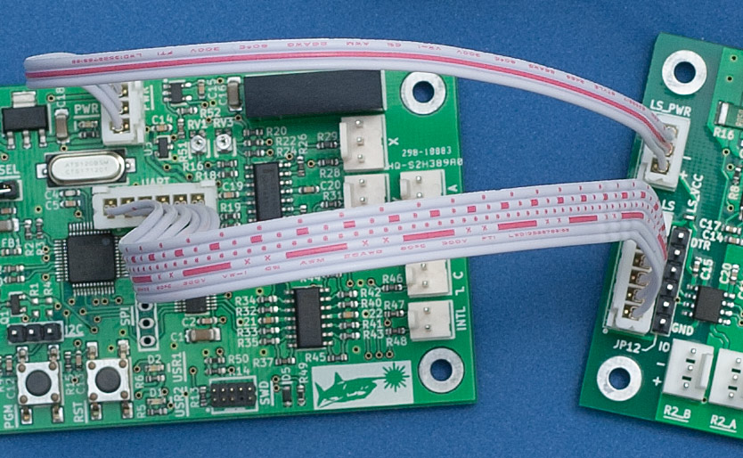
Connecting the Twostep board to a Lasershark:
The Twostep board comes with all cables/connectors necessary to connect the board to a Lasershark. Before you can connect these boards however you will need to solder two connectors onto your Lasershark unit. The first of these connectors is a 3-pin JST-XH connector which is used to supply power to the isolated UART section of the Twostep board. The second connector is a 6-pin JST-XH connector which is used for data communications. Please see the image below to identify the placement and proper orientation of these connectors:
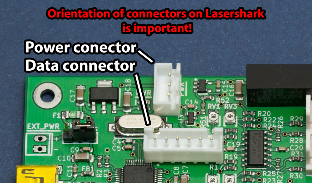
Once soldered on, simply connect the included 6 and 3 pin data cables between the Lasershark and Twostep board and you should be good to go!
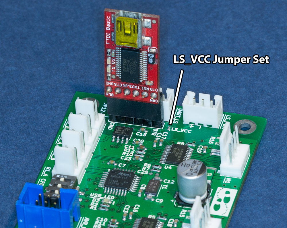
Connecting the Twostep board to an FTDI breakout or other UART device for control or programming:
The Twostep board has an isolated UART header which is compatible with FTDI breakout boards such as those sold by Sparkfun. This header may be used to both control the device as you would via a Lasershark and also to program new firmwares.
By default the power pin present on the FTDI breakout boards is not connected to the isolated UART's VCC rail. As a result, a Lasershark board power cable must be connected to provide power for this portion of the circuit. By jumping the LS_VCC jumper with a solder blob you can enable use of the FTDI breakout board's power pin and avoid having to use a Lasershark board.
Warning: With the LS_VCC solder blob jumped DO NOT connect the lasershark power connector and FTDI breakout board at the same time!
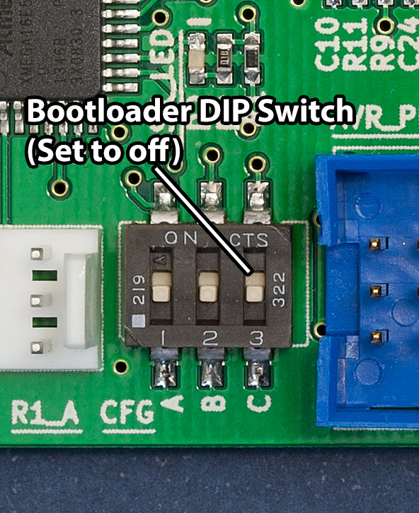
In order to program the board using the xboot bootloader Configuration switch C will need to be enabled. During normal operation this switch should be set to the OFF position.
Connecting limit switches to the Twostep:
The Twostep board has 4 limit switch connectors. These are intended to be attached to limit switches placed at travel limits in linear motion applications. Connections R1_A and R1_B are associate with Stepper motor M1 while R2_A and R2_B are associate with stepper motor M2.
Each connector consists of a Signal (IO), GND (-), and +3.3V (+) pin. The pins may be identified by the silkscreen labels on the left-hand side of the array of connectors:
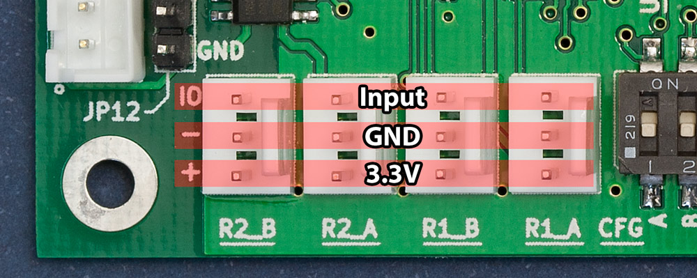
This combination of pins allows for the use of mechanical lever, optical, or magnetic limit switches. Internally, these signal pins are pulled high to 3.3v and are considered "triggered" when lines are pulled down to GND.
Warning: Never pull the signal line higher than +3.3v or lower than GND!
In order to easily disconnect your limits switches from the twostep board you may solder the included 3-pin polarized headers (Molex Inc. 0022272031) to the board. The mating connector components for this style of polarized header are:
-
3-pin female connector housing
- - Digikey WM2626-ND (Molex Inc. 0022012035)
-
Crimp pins
- - Digikey WM2623-ND (Molex Inc. 0008500031)
Connecting stepper motors to the Twostep:
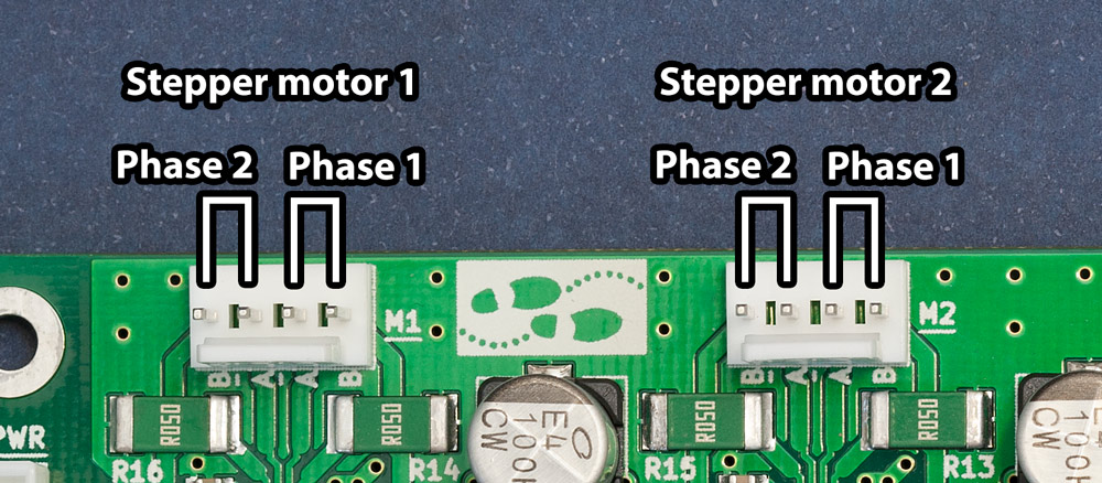
The Twostep board has two bipolar stepper motor connectors marked M1 and M2. Each connector is capable of driving stepper motors up to a max current of 2A (However you will likely need to add a heatsink or even active cooling system to reach anywhere near this current limit).
The majority of bipolar stepper motors you will run across will have four wires attached to them. If you use an ohm meter you will find that there are two pairs of wires that have little to no resistance between them (referred to as a phase from this point forwards). On the Twostep board stepper motor connectors you will see there are two pairs of "A" and "B" pins where one set has an underline beneath the letters and the other does not.
You should connect one of these motor phases to one of these AB pin sets and the other motor phase to the other AB pin set. For each connector it does not matter which phase goes with which AB pin set (although this will impact which direction the stepper steps when the direction pin is set high/low).
It also does not matter if wires within a phase are flipped. For example if you have a phase with wires that are blue and yellow, it does not matter if you connect blue to A and yellow to B or if you connected yellow to A and blue to B.
Warning: NEVER CONNECT OR DISCONNECT stepper motors from the board while power is applied! The stepper motor drivers on the Twostep will be damaged.
In order to easily disconnect your stepper motors from the twostep board you may solder the included 4-pin polarized headers (Molex Inc. 0022272041) to the board. The mating connector components for this style of polarized header are:
Powering the Twostep:
The Twostep board requires two different power sources. The first is for the isolated UART section which requires between 3.3 to 5v. If you are using a Lasershark unit, you can use the supplied 3-pin power cable to provide this power. If you are using an FTDI breakout board, you can place a solder blob on the LS_VCC jumper and the FTDI breakout board will provide this power.
The other power source is for the stepper motors and digital logic circuitry and is applied via the MOT_PWR connector. Any power supply that has a voltage output between 8v and an absolute max of 35V should work provided it is capable of supplying enough current to run your desired stepper motors. When connecting your power supply please pay close attention to the polarity of your connectors!
If you found this project interesting or helpful and have the means feel free to donate!