Pinout:
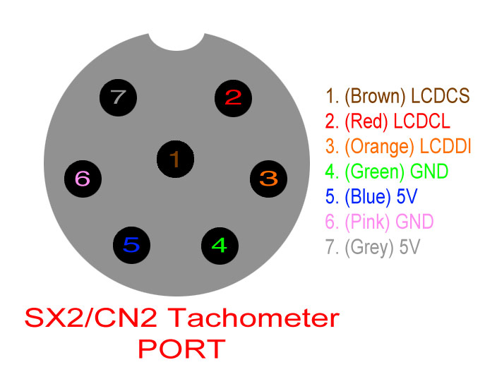
On the back of the side panel of the SX2 mini mill there is a 7-pin din port. This is used to attach an external tachometer display to the mill. This same port and protocol is used on the SC2 Late as well. The pinout and internal cable colors for this port are described in the image below. To reiterate, this is a visualization of the connector on the mill where the black circles represent male pins of the port:
Electrical line specifications:
-
2 GND
-
2 5V+
-
1 LCDCS - Frame indicator, a 5V digital line that is normally pulled high.
-
1 LCDCL - Clock line, a 5V digital line that is normally pulled high.
-
1 LCDDI - Data line, a 5V digital line that is normally pulled high.
Data specifications:
Once the SX2 mill (or SC2 lathe) is turned on, a blip of data is sent over the LCDCS, LCDCL, and LCDDI lines every 0.75s. This blip will hereby be called a packet.
Around August 2014 Sieg Industries added a 36 bit header to the start of each packet. Prior to this time no such header existed.
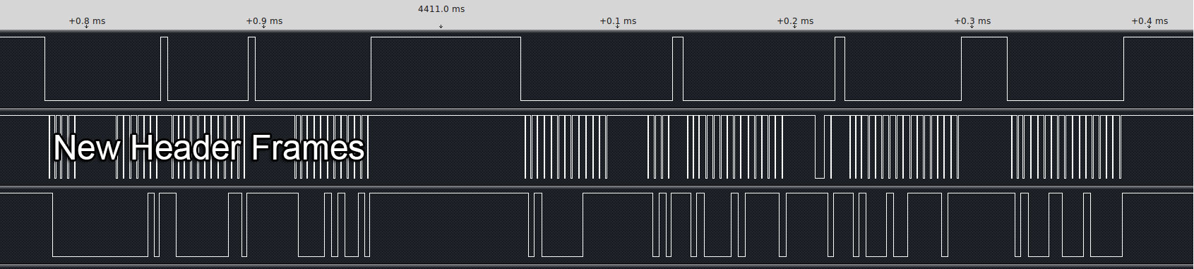
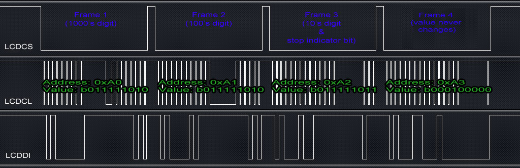
Following this header (if present) are 4 frames. Each frame start is indicated by the LCDCS line being pulled down. The frame ends are indicated when this line is pulled back up. Each frame consists of 17 bits of data. A bit is read by reading the state of the LCDDI line on every fall of the LCDCL line.
The first 8 bits of each frame represent the address of the frame. The following 9 bits represent the frame's data. The SX2 Mill only uses 4 addresses and always transmits them in the same order (0xA0, 0xA1, 0xA2, 0xA3). These addresses respectively indicate the 1000's rpm digit, 100's rpm digit, 10's rpm digit, and one additional register which the SX2 mill always transmits with a value of 0x20.
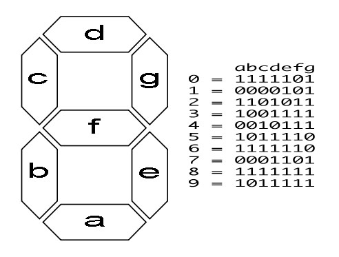
The 9 data bits of each rpm digit frame are structured such that:
-
The first data bit is always 0
-
The next 7 bits identify which of the 7 segments of the digit should be turned on (1) or off(0). An image below describes what bits toggle what segments.
-
The 9th data bit is always 0 EXCEPT for when the spindel is not rotating. In this scenario, the 10's place digit's final bit is 1.
Update: 11/9/2015:
Wes contacted me to mention he has been trying to control control a tachometer display by simulating the mill output. He found that setting certain data bits of the 4th frame (0xA3) control additional LCD elements which I was unaware existed! These include:
- 1st - Always 0
- 2nd - Always 0
- 3rd - Always 0
- 4th - Always 0
- 5th - Light “forward” indicating that the spindle is running counterclockwise (CCW)
- 6th - Light up the 4th digit as 0 (e.g., multiply speed by 10) (this is the 0x20 you found, without it you only get 3 digits on the display)
- 7th - Light “tapping” (doesn’t appear as if there is any dedicated functionality for tapping in the mill)
- 8th - Light “reverse” indicating that the spindle is running clockwise (CW)
If you found this project interesting or helpful and have the means feel free to donate! CNC builds are expensive!