V1 Kits:
Notice: This is the OLD tachometer design which is present for reference only. Please consider purchasing a v2 tachometer kit! They are smaller, less expensive, and offer more features! Simply click the "Buy a V2 Kit" tab above this text. Thank you!
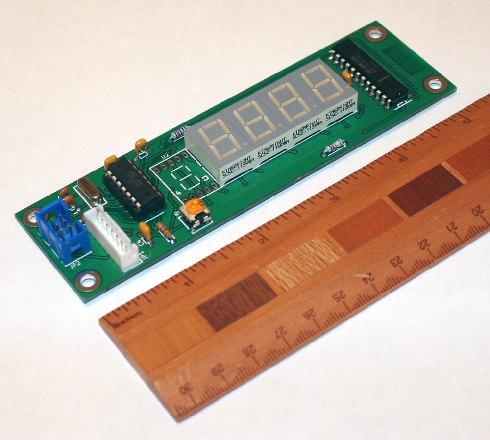
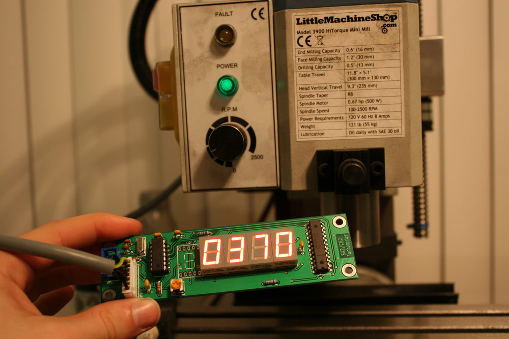
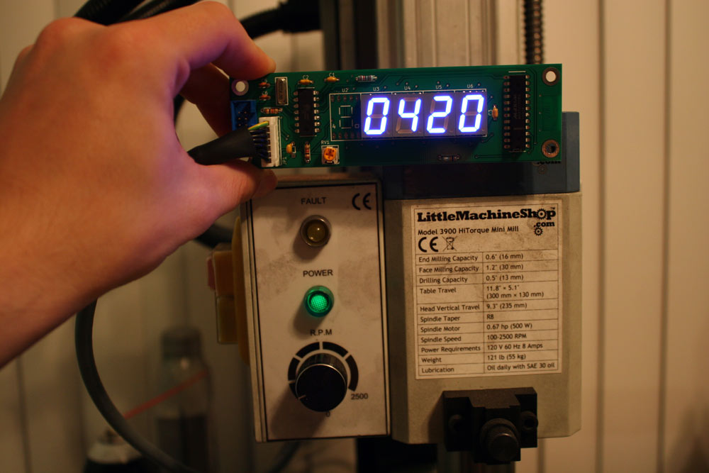
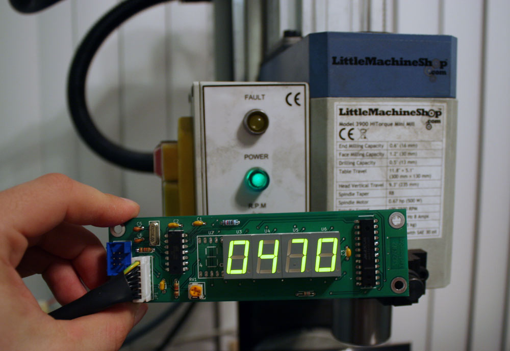
Note the red/blue 7-Segments look a bit different in person (they are easier to read). I think they are camera shy.
Kits and assembled units are avaliable now. They include everything you need except an enclosure for the tachometer. That includes the pcb+all components, a pre-programmed microcontroller to work with sx2 mills and cn2 lathes, your choice of red/green/blue 7-Segments, a pre-built tachometer cable and strain relief. The kit also comes with a 3-pin XH JST connector+ wire which can be used to add a forwards/reverse switch to the SX2 Mini mill. You can purchase one via the "Buy Now" paypal button below or email me via the contact page if you have questions.
<form action="https://www.paypal.com/cgi-bin/webscr" method="post" target="_top">
<input type="hidden" name="cmd" value="_s-xclick">
<input type="hidden" name="hosted_button_id" value="7S28F4KVZE4NQ">
<table>
<tr><td><input type="hidden" name="on0" value="SX2/CN2 Tachometer">SX2/CN2 Tachometer</td></tr><tr><td><select name="os0">
<option value="Blue 7-segments - Assembled">Blue 7-segments - Assembled $50.00 USD</option>
<option value="Blue 7-segments - Unassembled">Blue 7-segments - Unassembled $50.00 USD</option>
<option value="Red 7-segments - Assembled">Red 7-segments - Assembled $45.00 USD</option>
<option value="Red 7-segments - Unassembled">Red 7-segments - Unassembled $45.00 USD</option>
</select> </td></tr>
<tr><td><input type="hidden" name="on1" value="I would like the cable connector...">I would like the cable connector...</td></tr><tr><td><select name="os1">
<option value="Soldered to the top of the pcb (The side with components)">Soldered to the top of the pcb (The side with components) </option>
<option value="Soldered to the bottom of the pcb (The side with no components)">Soldered to the bottom of the pcb (The side with no components) </option>
<option value="Unsoldered">Unsoldered </option>
</select> </td></tr>
</table>
<input type="hidden" name="currency_code" value="USD">
<input type="image" src="https://www.paypalobjects.com/en_US/i/btn/btn_buynowCC_LG.gif" border="0" name="submit" alt="PayPal - The safer, easier way to pay online!">
<img alt="" border="0" src="https://www.paypalobjects.com/en_US/i/scr/pixel.gif" width="1" height="1">
</form>
<br>
- How much do these cost?
-
Please click the PayPal "Buy Now" button to view the cost. You do not need to enter creditcard or paypal info to view the price.
- How much is shipping?
-
Shipping costs depend on where you are in the world and shipping option selected for international customers. Please click the PayPal "By Now" button to enter your address to recieve a calculated shipping price.
- How are these shipped?
-
U.S. Orders are shipped via USPS Priority using Small Flat Rate Boxes.
-
International orders at checkout can choose between USPS International 1st class shipping (slow, but less expensive), or USPS International Flat Rate Priority (more expensive but faster).
-
UPS/FedEx IE/IP shipments are possible for larger orders or expedite needs however please be aware these services are $$$!
- How do I pay for shipping?
-
Shipping is automatically added during the checkout process according to where you have the package shipped to. You will be able to see the cost of shipping BEFORE completing the checkout process.
- What models is this compatible with?
A NON-EXHAUSTIVE list includes the following. If you would like to know if your mill is supported please feel free to email me!:
Assembly:
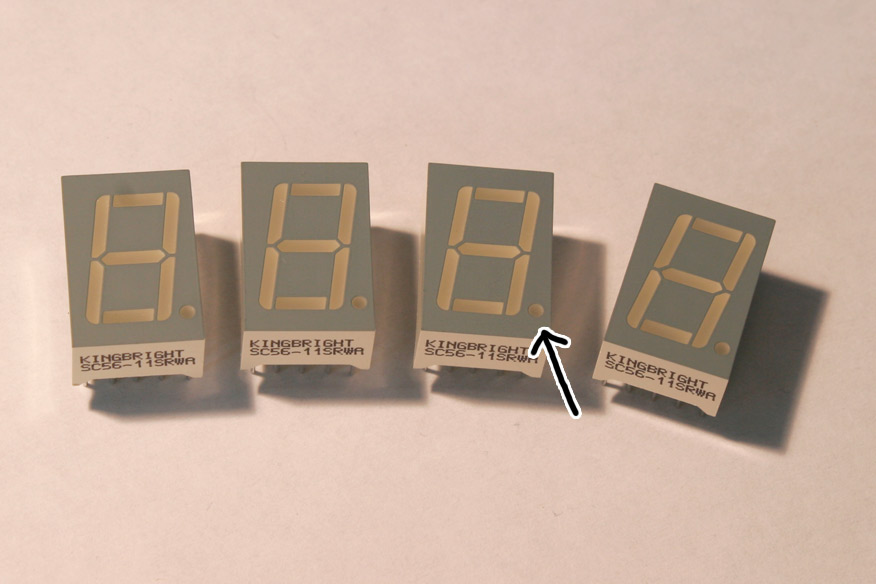
Install the 7-segment displays in the areas marked U3, U4, U5, and U6. DO NOT POPULATE U2. Before soldering, verify the decimal spot on the 7-segment matches up with the decimal point on the PCB board. Scotch tape is useful to align the elements while soldering.
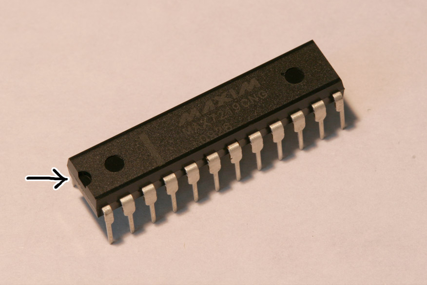
Install the MAX7219 IC in the area marked U1. Before soldering, verify the side of the IC with a notch on it is on the same side as the rectangular orientation marker on the U1 silkscreen.
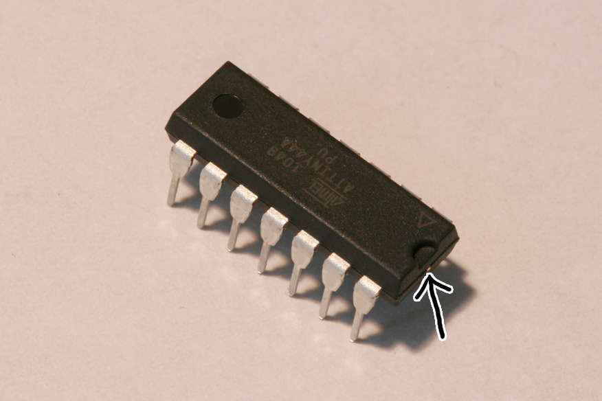
Install the ATtiny IC in the area marked U7. Before soldering, verify the side of the IC with a notch on it is on the same side
as the rectangular orientation marker on the U7 silkscreen.
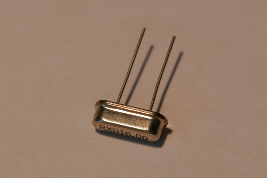
Install the 16Mhz crystal in the area marked Y1. The orientation of this part does not matter.
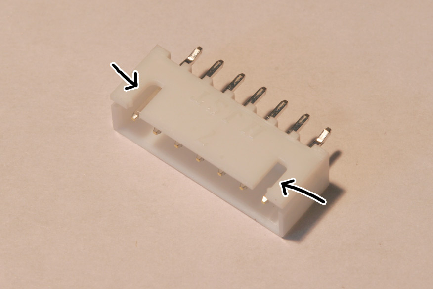
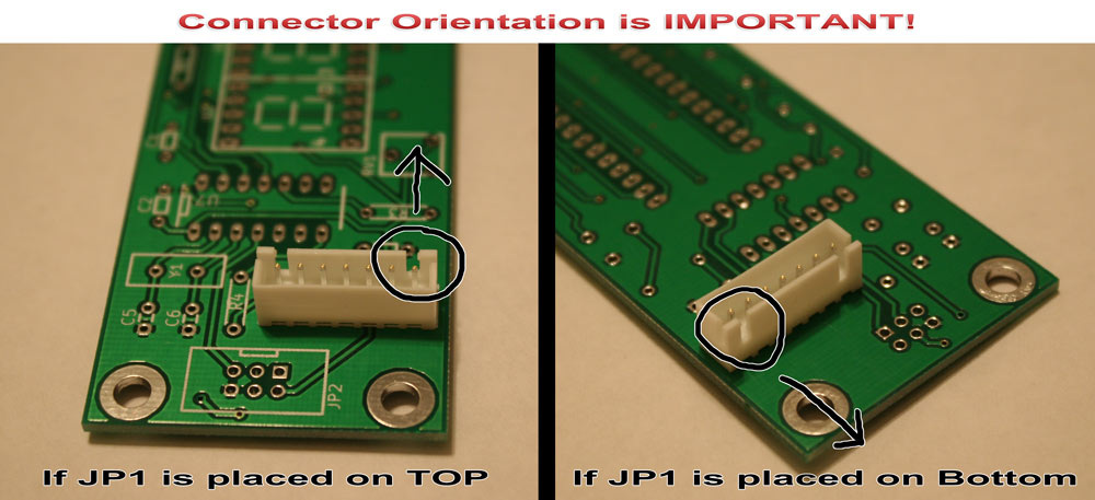
Install the 7-pin jst xh header in the area marked JP1. This part can be placed on the top or bottom of the PCB according to what makes routing easier inside of your tachometer enclosure. IT IS CRITICAL TO ALIGN THIS PART CORRECTLY! Position the header (take note of the notches) according to the images below:
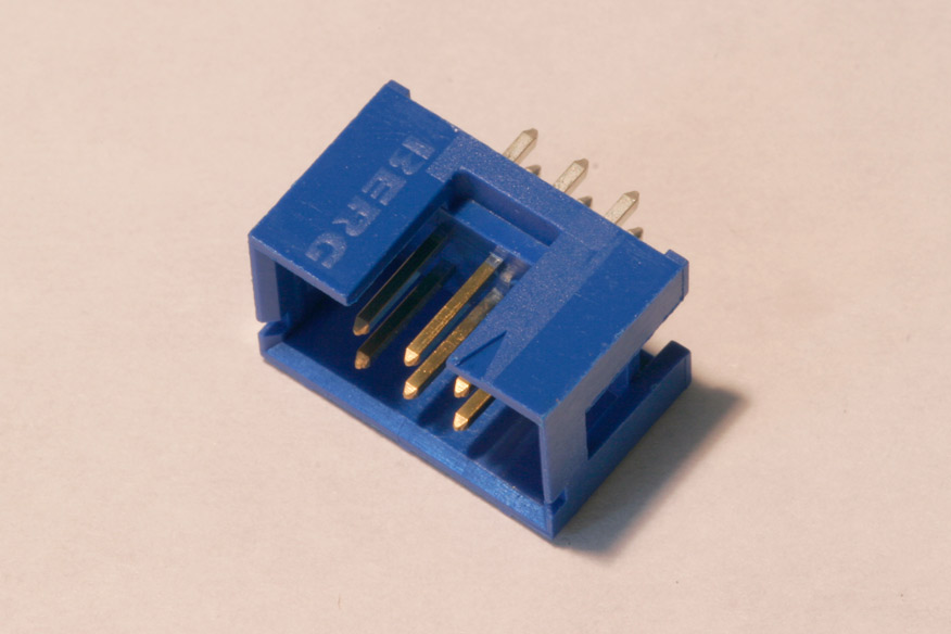
Optionally, install the 2x3 avr mini-isp programming header on your board. When installing, verify the notch on the header aligns with the silkscreen orientation marker.
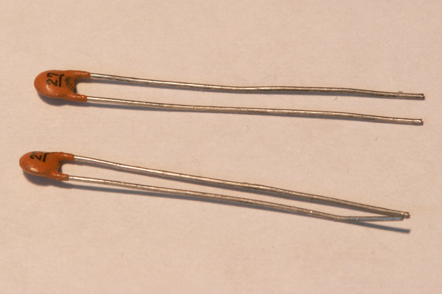
Install the 27pF capacitors in the areas marked C5 and C6. The orientation of these components does not matter.
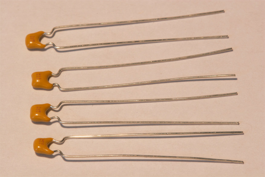
Install the 0.1uF capacitors in the areas marked C1, C2, C3, and C4. The orientation of these components does not matter.
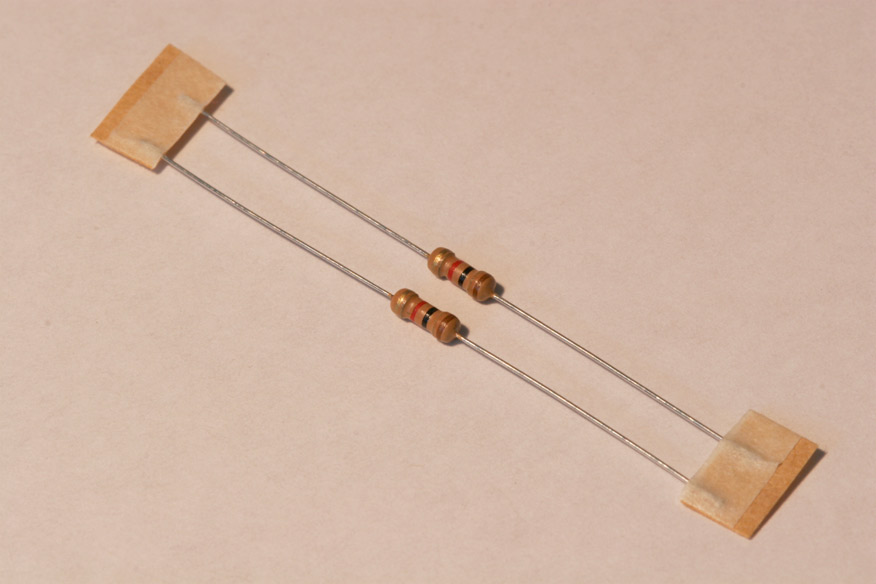
Install the 1K resistors in the areas marked R3 and R4. These resistors can be identified by their 4 color bands (Brown, Black, Red, Gold). The orientation of these components does not matter.
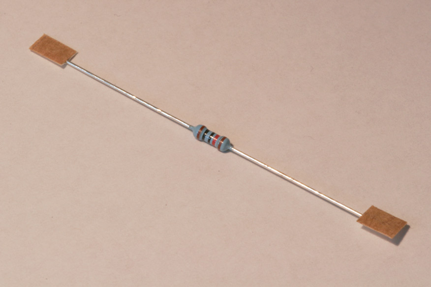
Install the 10K resistor in the area marked R1. This resistor can be identified by it's 5 color bands (Brown, Black, Black, Red, Brown) The orientation of this component does not matter.
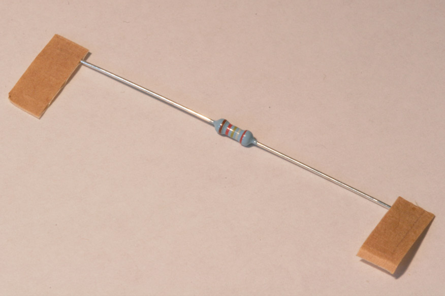
Install the 29.4K resistor (for red 7-segments), 27K (for green 7-segments), or 20K (for blue 7-segments) in the area marked R2. This resistor can be identified by it's 5 color bands (29.4K = Red, White, Yellow, Red, Brown) (27K = Red, Grey, Black, Red, Brown) The orientation of this component does not matter.
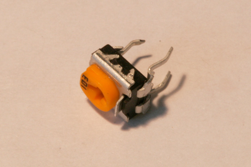
Install the potentiometer in the area marked RV1.
Testing:
Please read through the following before performing the test:
1. Power off the mill or lathe after stopping the spindle from rotating.
2. Verify soldering and orientation of components.
3. Plug the provided 7-pin connector into the sx2/cn2 tachometer board header.
4. Connect the 7-pin DIN connector to the mill/lathe.
5. Power on the mill. Within a second you should see the 7-segments turn on and display 0000. If you do not see this, TURN OFF THE MACHINE and email me along with what you see and I can help you out.