Intro:
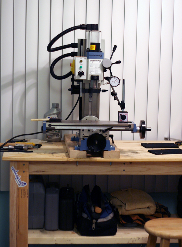
Despite living in an apartment, I have given serious thought over the years to purchasing an X2 milling machine to CNC-ify. When I learned that Little Machine Shop had begun selling the SX2 mill which sports more travel, a better motor (500w brushless), and a belt drive compared to the standard X2, I caved and purchased it.
I knew before purchasing this mill that it had a tachometer display port on it much like the SC2 Lathe has. I also knew there was no way in hell I was going to pay 125$ for what amounts to an lcd and simple uC. So what's the logical thing to do in a situation like this? Hack it!
Step 1 - Trace the wires:
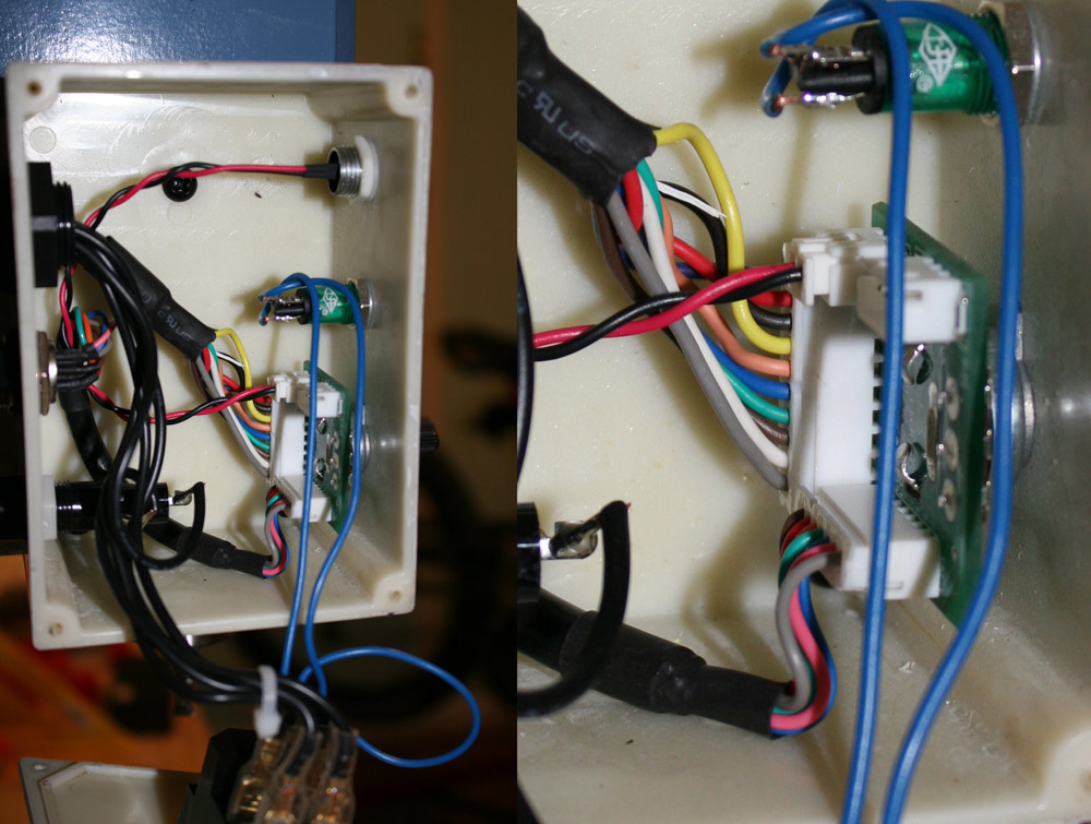
I pulled the side panel off to see where the tachometer wires were going and found they connected to the Potentiometer board which is used to control the speed of the SX2 mill. This board has 4 unmarked jst xh series connectors (thanks for finding the connector types Don) on it that include:
-
10 pin header that connects to the circuitry on the back of the unit.
-
7 pin header that connects to the tachometer plug
-
2 pin header for the fault led
-
3 pin mystery header
Step 2 - Become sidetracked:
What could this unmarked 3 pin mystery header be for? The center pin is connected to ground and the other two pins appear to be i/o lines that are pulled up to 5v via 4.7k resistors. Hey wait, doesn't the SC2 lathe which uses the same 500w brushless motor have a forwards/reverse switch? Hmm, and Little Machine Shop sells the SX2 and CN2 potentiometer and motor controller boards as the same product!
As it turns out, you can easily make the SX2 mill run in forwards or reverse just by grounding one of these pulled up i/o lines. Connecting the i/o line towards the inside of the case to ground (center pin) will cause the machine to run in reverse. Connecting the i/o line towards the outside of the case to ground (center pin) will cause the machine to run normally.
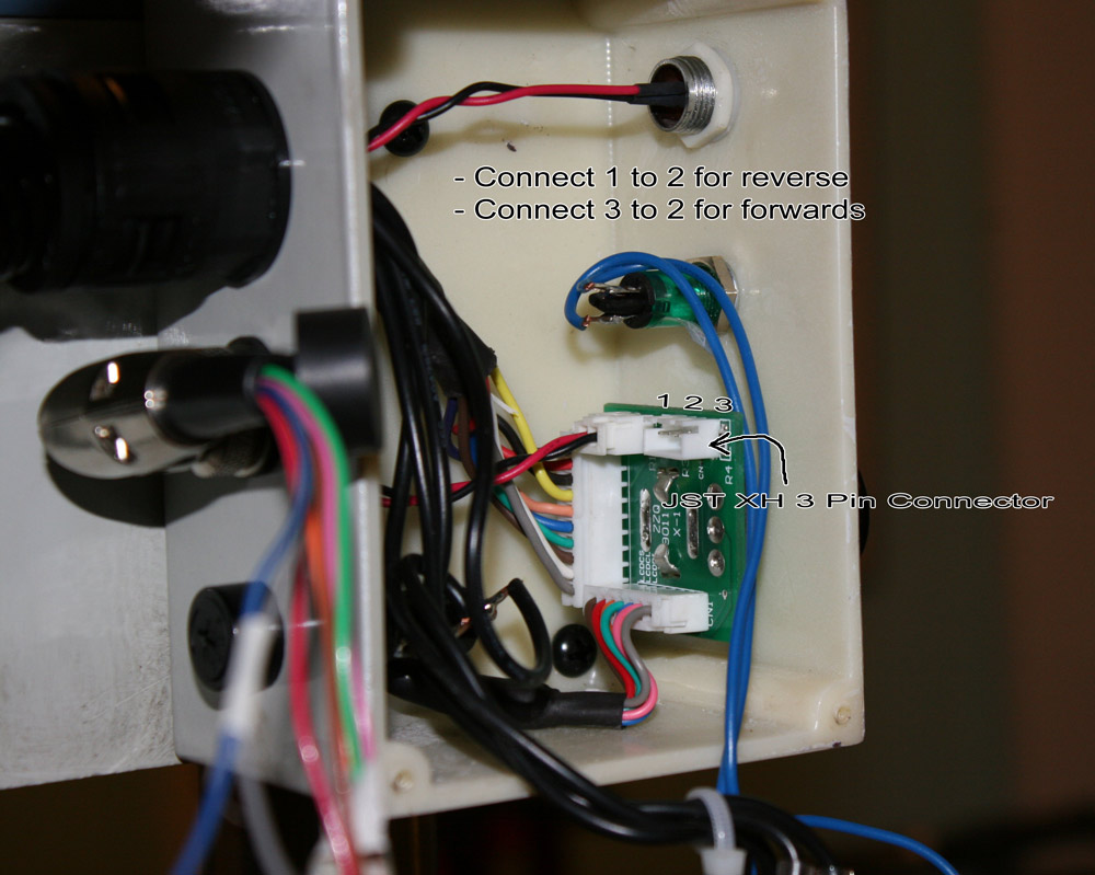
I wonder why they left this feature out? All that needs to be done to gain the functionality is to wire up a dirt-cheap two position three prong switch to the 3 pin connector.
Step 3 - Back on track:
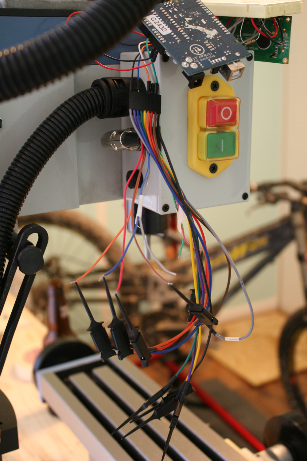
With that distraction gone, I finished up tracing the wires and identifying what voltages (and signals) were present on the lines using a DS1052E DS1102E (he he he) scope:
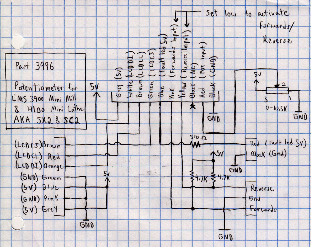
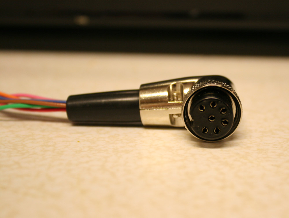
Upon completing this, I knew the tachometer port offered two ground lines, a 5v line, and three 5v digital lines (LCDCS, LCDCL, LCDDI) which would need to be decoded to display readings. To analyze these lines, I made a custom tachometer cable using a mating "7 pin mic connector" that I purchased off ebay. Officially this connector is would be considered a 7-pin DIN connector, but I had more luck searching for the item as a "XLR 7-pin mic connector".
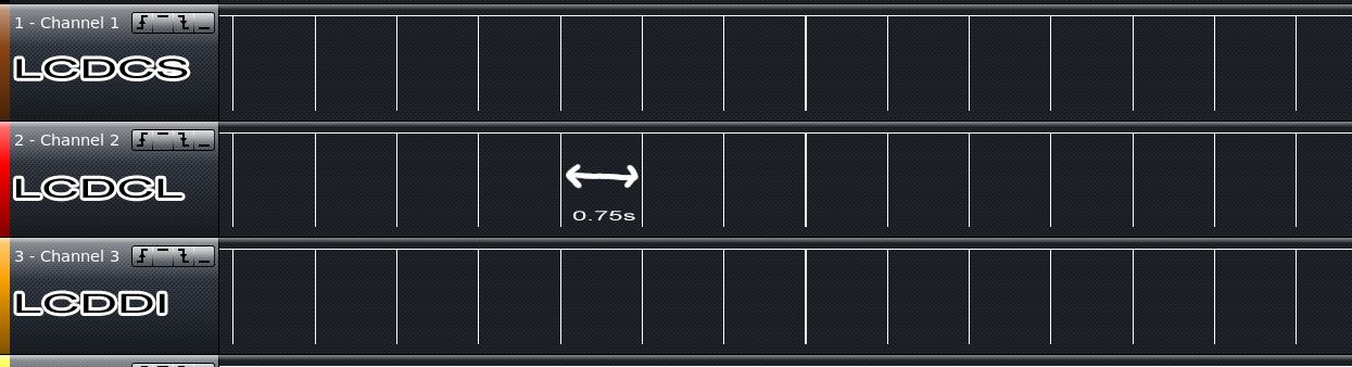
A quick look at the digital lines using a
Saleae logic analyzer indicated that a burst of data is sent every 0.75 seconds as soon as the machines turn on. I'll call these bursts "packets" from here on out.
 Note: Since writing this Sieg Industries has changed the tachometer protocol. This seems to have happened around August 2014 based on customer reports. The details of the new protocol are present on the Pinout and Protocol Page.
Zooming in a bit further revealed that LCDCS appeared to be some sort of frame line and that each packet consists of 4 frames. LCDCL, being the fastest toggling line, seemed like a likely clock line candidate and the sporadic nature of LCDDI made it a good data line condendor.
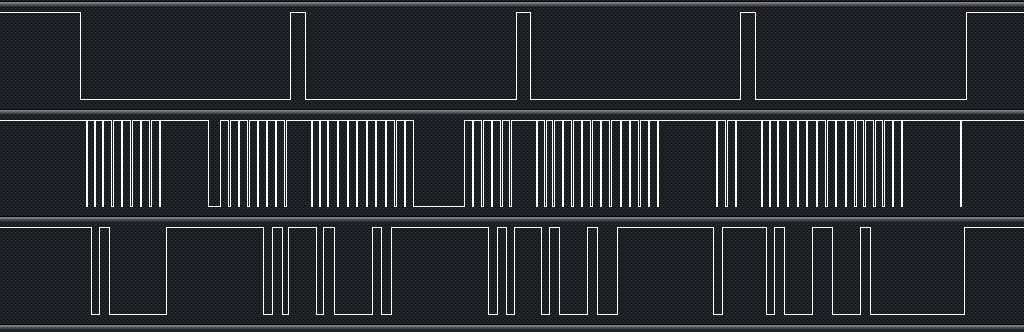
To give some sort of validations to these educated guesses, I tried decoding a few of the packets sampled when the spindel was at rest and then again when the spindel was rotating.
On a positive note, I found that by reading the data line (LCDDI) on every falling edge of the clock line (LCDCL), I was able to consistently read out the 4 17 bit frames. Thankfully, while the spindle was stopped, these values did not change.
Packet when spindel was not spinning:
10100000011111010, 10100001011111010, 10100010011111011, 10100011000100000
Looking at this data closer, I noticed the first 8 bits increment by one. This made me guess they were addresses and the last 9 bits were data. To confirm this I ran the spindle at different speeds and found that while the last 9 bits of each frame changed, the first 8 always stayed the same.
Packet when spindel was not spinning:
10100000:011111010, 10100001:011111010, 10100010:011111011, 10100011:000100000
Step 4 - Decoding the data:
It was at this point I wrote a simple atmega168 program to read the frames and dump them to the terminal so I could observe how the data changed as I adjusted the spindle speed.
From pictures and data gathered around the web, I was under the impression that:
-
The tachometer display rpms increment by 20 (according to LMS)
-
The display had 4 7-segments to represent the rpms
-
The display could show a forwards, reverse, and stop symbol
I tried using this information to decode the signals, but something just seemed off. In the end I emailed Frank Hoose from
http://www.mini-lathe.com in the hopes they still had their tachometer lying around. Luckily for me they did and were nice enough to clarify a few questions I had:
-
The tachometer display rpms actually increment by 10
-
The display does indeed have 4 7-segments to represent rpms
-
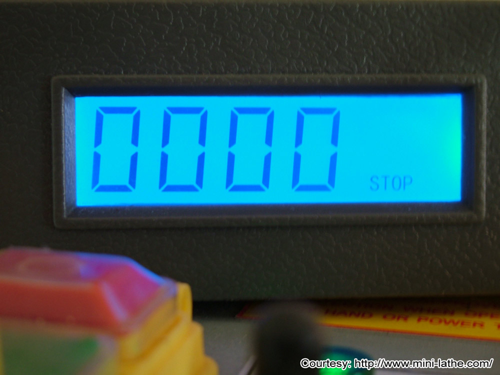
The display does display a separate STOP symbol when the spindle is at rest but it DOES NOT display forwards/reverse.
-
The display updates at least 1 time a second.
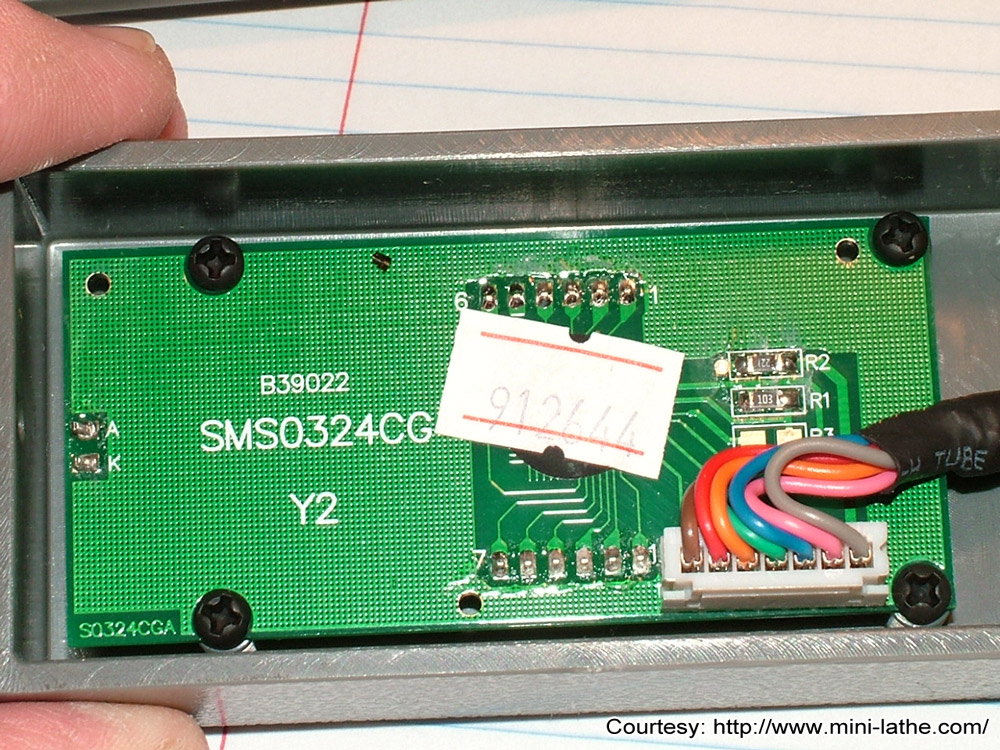
They also took some pictures of the tachometer guts and display without me asking which was nice.
Armed with this new information and a tachometer a buddy offered to lend me, I was able to quickly figure the rest out. The first 3 frames turned out to represent the 1000's, 100's, and 10's display digits. The final frame value never seems to change so I'm going to guess this is a "write to screen" control frame.
The first bit of digit frame data is always 0. The next 7 bits toggle the 7 segments of the digit on/off. To figure out what bits controlled what segments, I incremented my spindel speed by 50 rpms up to 950 rpms and recorded what the 100's place digit displayed.
The last bit of digit frame data is always 0 EXCEPT for the 10's place frame. When the spindel is rotating, this bit is 0 but when stopped, the bit is set to 1.
Step 5 - Test findings:
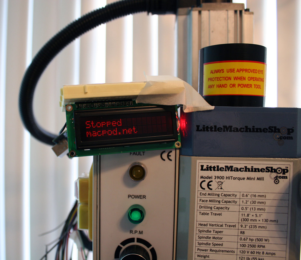
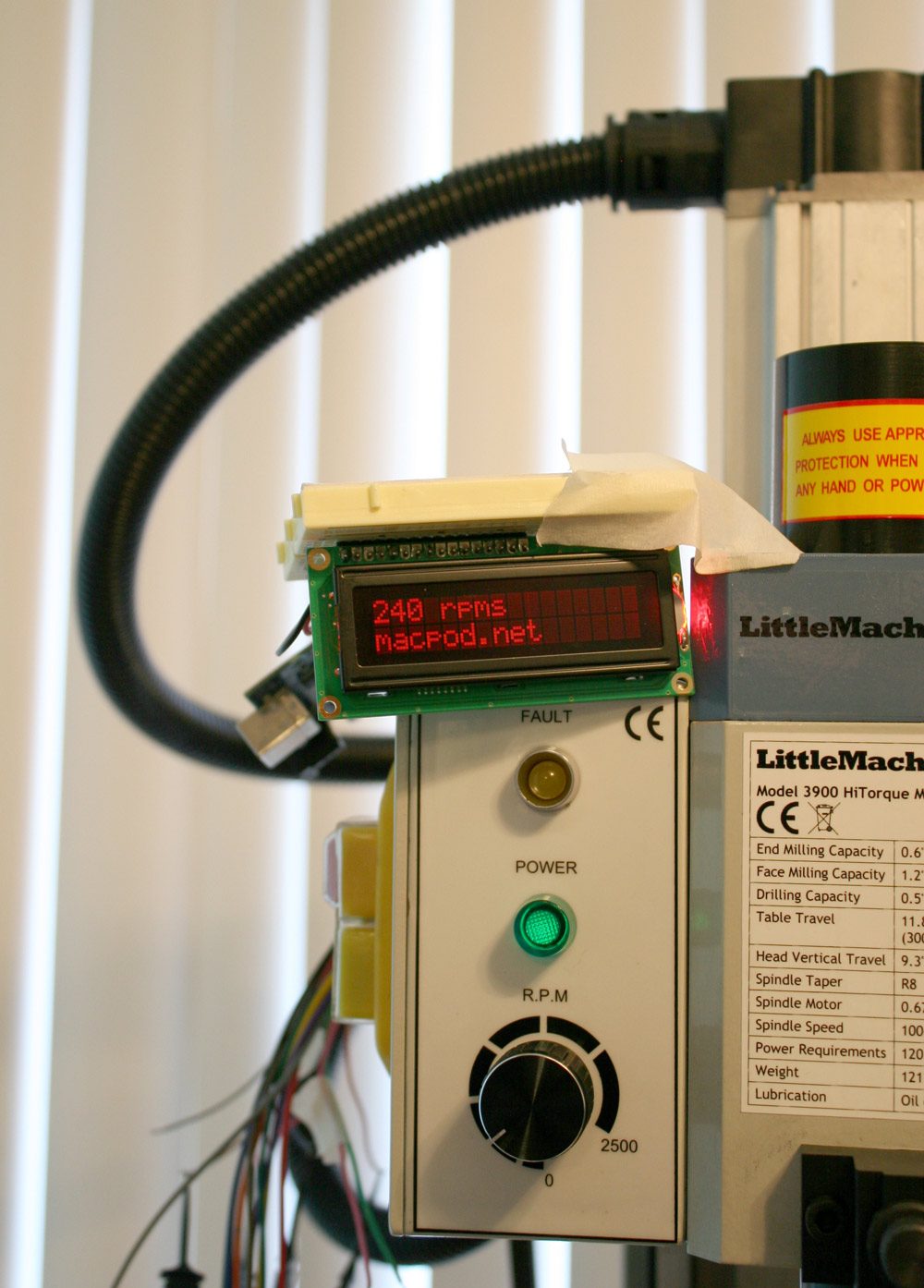
I wrote a quick and dirty arduino app (click for code) that connects to the port, processes the packets, then displays the data.
Here's what it looks like with the spindle at rest and while running (click on the images for larger versions):
Step 6 - Document the pinout and protocol
I figured it would be better to keep the "journey" log separate from the pinout/protocol data so I wrote this up on the pinout_and_protocol page.
The future:
I plan on designing and fabricating my own tachometer display which should cost nowhere near the ~125$ vendors want for these. It would be nice if I could sell these in order to pay for this mill and fund my cnc build.
Kits are in! email me for info.
In addition, I plan on exploring the controller board of this machine some more. It is designed in a very practical manner where the motor driving circuit is on a main board and the brains of the operation (an Atmega8) is placed on an easily removed daughterboard. Surely some interesting hacks will arise from this design! :)
If you found this project interesting or helpful and have the means feel free to donate! CNC equipment is expensive!